Table of Contents
Advertisement
Quick Links
Installation and Operation Manual
Web-enabled two channel AES/EBU and one channel analog to digital silence monitor/switcher.
For firmware versions equal to or greater than 0.6.
If you need a firmware upgrade, contact Broadcast Tools®
No part of this document may be reproduced or distributed without permission.
ALL SPECIFICATIONS AND FEATURES FOR THIS PRODUCT ARE SUBJECT TO
NOTE: We recommend the use of Chrome, Firefox or Safari as your browser.
Due to the dynamic nature of product design, the information contained in this
document is subject to change without notice. Broadcast Tools, Inc., assumes no
responsibility for errors and/or omissions contained in this document. Revisions
of this information or new editions may be issued to incorporate such changes.
Broadcast Tools® is a registered trademark of Broadcast Tools, Inc.
All Sentinel® labeled products are registered trademarks of Broadcast Tools, Inc.
Copyright® 1989 - 2019 by Broadcast Tools, Inc. All rights reserved.
No part of this document may be reproduced or distributed without permission.
Visit www.broadcasttools.com for important product update information.
P R O B L E M S O LV E D
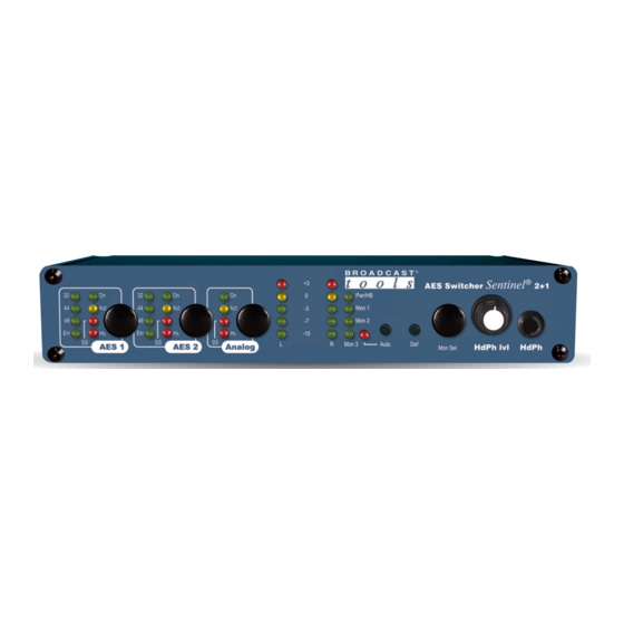
AES Switcher Sentinel
Manual update: 1/31/19
CHANGE WITHOUT NOTICE
®
2+1
®
Advertisement
Table of Contents

Related Manuals for Broadcast Tools AES Switcher Sentinel 2+1


Summary of Contents for Broadcast Tools AES Switcher Sentinel 2+1
- Page 1 NOTE: We recommend the use of Chrome, Firefox or Safari as your browser. Due to the dynamic nature of product design, the information contained in this document is subject to change without notice. Broadcast Tools, Inc., assumes no responsibility for errors and/or omissions contained in this document. Revisions of this information or new editions may be issued to incorporate such changes.
-
Page 2: Table Of Contents
AES Switcher Sentinel ® 2+1 Installation and Operation Manual Table of Contents Section Title Page # Introduction............3 Safety Information . -
Page 3: Introduction
Products, as with any product will give you many years of dependable service. This manual is intended to electronic device, can give you all the information needed to install and operate the Broadcast Tools® AES fail without warning. Switcher Sentinel 2+1®. -
Page 4: Product Overview
AES input it can automatically switch to the back-up AES input or the backup ADC input. The AES Switcher Sentinel 2+1 can be configured and monitored locally and/or remotely over any IP network, including private net- works, IP-based industrial control networks, and the Internet. -
Page 5: Inspection
UPS Standby Power System We recommend that you connect your AES Switcher Sentinel 2+1® to a UPS sys- tem. A UPS helps minimize the risk to the AES Switcher Sentinel 2+1® and pro- vides AC power during a power outage. -
Page 6: Led Indicators
AES Switcher Sentinel ® 2+1 Installation and Operation Manual LED Indicators • “Pwr/HB” LED: Illuminates when power is applied and flashes to indicate microprocessor operation. (Green) • “Mon 1” LED: Lit when Input 1 audio is routed to the headphones/analog monitor outputs (Green) •... -
Page 7: Xlr Connector Pinout/Cable Prep
The station ground should be con- nected to the designated “Chs Gnd” ground terminal. AES/EBU Inputs and Outputs The AES Switcher Sentinel 2+1’s two AES/EBU inputs and output have 3-pin XLR jacks. AES In 1 = Primary AES input (AES Silence Sensor 1) XLR-F... -
Page 8: Adc Analog Input
32 to 96kHz. Enabled via SW7-1. Analog Stereo Monitor Output “Monitor Out” RJ45 The AES Switcher Sentinel 2+1 features an RJ45 fixed level (+4 dBu nominal) bal- anced line level analog monitor audio output that can switch between Input 1 (AES 1), Input 2 (AES 2), and Input 3 (Analog) audio via front panel, web and remote con- trol. -
Page 9: Remote Control Connections
2+1 Installation and Operation Manual Remote Control Connections The AES Switcher Sentinel 2+1® has three SPST Normally Open (NO) relay con- tact closure remote control outputs located on the top 6-position pluggable screw ter- minal block (TB2 top). When a relay is active it will make connection between its NO contact and its common (CM). -
Page 10: Operation
2+1 Installation and Operation Manual Operation The AES Switcher Sentinel 2+1® can be controlled from a web browser, front panel controls, and/or remote-control connections. The slow blinking front panel “PWR/HB” LED indicates valid power and proper operation. The front panel is equipped with push button controls and indicator LEDs. -
Page 11: Ethernet "Quick Start" Guide
CAUTION! NEVER DOWNLOAD FIRMWARE UPDATES OR CHANGES TO THE BNET WEBSERVER UNLESS INSTRUCTED TO DO SO BY BROADCAST TOOLS®. DOING SO DELETES ALL SOFTWARE AND VOIDS ALL WARRANTIES FROM BROADCAST TOOLS, INC. CAUTION! If you are not familiar with Ethernet enabled equipment, it may be use- ful to contact your IT department, network administrator or network consultant for assistance. - Page 12 AES Switcher Sentinel ® 2+1 Installation and Operation Manual Step 2: Click on the sidebar labelled Change adapter settings. The Network Connections windows will pop up, as shown below. Step 3: Right click on the icon labeled Local Area Connection or Ethernet. A menu will appear.
- Page 13 AES Switcher Sentinel ® 2+1 Installation and Operation Manual Step 4: On the Local Area Connection Properties page, double click on Internet Protocol (TCP/IPv4) to display properties. WEBSITE: Step 5: Before making any changes to the network settings, write down the current Visit our web site for settings (or screen capture the page and print) so that they can be restored product updates and...
-
Page 14: Opening The Login Web Page
AES Switcher Sentinel ® 2+1 Installation and Operation Manual Web Setup and Operation Ethernet (NETWORK) port LED indicator functions NOTE: We recommend the use of Chrome, Firefox, or Safari for as your browser. Opening the LOGIN Web Page 1. Connect the supplied GRAY colored XOVER cable between the PC’s Ethernet port and the products “NET”... -
Page 15: Login" Web Page
AES Switcher Sentinel ® 2+1 Installation and Operation Manual “Login” Web Page The Login screen displays the Username and Password entry points. WEBSITE: Visit our web site for product updates and additional information. WEB SETUP e-mail: voice: fax: support@broadcasttools.com 360.854.9559 866.783.1742... -
Page 16: Monitor/Control" Web Page
AES Switcher Sentinel ® 2+1 Installation and Operation Manual After you have successfully logged in, the Monitor/Control page will be displayed. Depending on your access level, you may or may not be able to control or modify the product’s configuration. “Monitor/Control”... - Page 17 AES Switcher Sentinel ® 2+1 Installation and Operation Manual Left/Right Level Meters: Display the left and right input audio levels for inputs one, two and three, respectively. In Phase/Below Threshold: Indicates if the input audio is Above Threshold/In Phase, Out of Phase, or Below Threshold. Input Labels: Input channel labels.
-
Page 18: User Setup" Web Page
AES Switcher Sentinel ® 2+1 Installation and Operation Manual “User Setup” Web Page NOTE: You may view a password by checking the “Show Password” box. Eight Usernames and Passwords may be configured for one of three access levels: “Admin” allows complete configuration access and control. WEBSITE: “Monitor/Control”... -
Page 19: I/O Setup" Web Page
AES Switcher Sentinel ® 2+1 Installation and Operation Manual “I/O Setup” Web Page The I/O setup page allows you to label and configure all three inputs/silence sensors, as well as configure the relay output and remote-control inputs. WEBSITE: Visit our web site for product updates and additional information. - Page 20 AES Switcher Sentinel ® 2+1 Installation and Operation Manual “I/O Setup” Web Page (cont.) RMT4 Input Function: Auto/Manual Toggle: Pulsing the RMT4 input toggles unit between Auto and Manual mode. EXTernal Sustained: Holding the RMT4 input low switches the unit to the backup input, releasing returns to the primary input.
- Page 21 AES Switcher Sentinel ® 2+1 Installation and Operation Manual “I/O Setup” Web Page (cont.) Silence Sensors: Input Label: Up to 20 characters may be entered to describe the input. Delay (Sec): When the input goes below threshold or out of phase the delay timer starts, if the input remains below threshold or out of phase for the duration of the delay then an alarm is gener- ated and, if in automatic (bounce) mode, backup switching...
- Page 22 AES Switcher Sentinel ® 2+1 Installation and Operation Manual “I/O Setup” Web Page (cont.) K4, K5 and K6 Configuration: Each relay, labelled K4, K5, and K6, respectively, may be programmed to operate when an input is silent, active (switched to) or inactive (not switched to).
-
Page 23: Email/Network Setup" Web Page
AES Switcher Sentinel ® 2+1 Installation and Operation Manual “Email/Network Setup” Web Page WEBSITE: Visit our web site for product updates and additional information. WEB SETUP e-mail: voice: fax: support@broadcasttools.com 360.854.9559 866.783.1742... - Page 24 AES Switcher Sentinel ® 2+1 Installation and Operation Manual “Email/Network Setup” Web Page – Device Network Settings Device Address: Enter a static IP address here. Default: 192.168.1.55 Device Netmask: Enter the Netmask here: Default: 255.255.255.0 Gateway Address: Enter the Gateway IP here: Default: 192.168.1.1 DNS Server IP Address: Enter your DNS address here.
- Page 25 AES Switcher Sentinel ® 2+1 Installation and Operation Manual “Email/Network Setup” Web Page – Email Logging Settings Logging Email Address: Email address for the “Logging” email recipi- ent (may be different from the 8 “Alarm” Recipient Addresses. Logging emails and Daily emails are sent to this address only.
- Page 26 AES Switcher Sentinel ® 2+1 Installation and Operation Manual “Email/Network Setup” Web Page – SNMP Manager Settings SNMP Enable: Enables or disables SNMP functionality, enabled by default. SNMP Enable Traps: When enabled, SNMP trap messages will be sent. When disabled, no trap messages will be sent to the manager IP. SNMP Trap IP Address: This is the IP address of the SNMP manager.
- Page 27 AES Switcher Sentinel ® 2+1 Installation and Operation Manual “Email/Network Setup” Web Page – Other Settings Site ID: This is the Site Identifier that is displayed on the web and in email. Monitor Refresh Time (Sec): Interval at which the Monitor page refreshes. Shorter times may increase network traffic.
- Page 28 .ncs file. Firmware: Browse to locate and apply a firmware update file saved on your computer. Be sure to follow the update instructions provided by Broadcast Tools. WEB SETUP e-mail: voice: fax: support@broadcasttools.com...
-
Page 29: Show Logs" Web Page
AES Switcher Sentinel ® 2+1 Installation and Operation Manual “Show Log” Web Page This page displays current alarms. Alarm Messages Active: Audio above silence alarm threshold. Silent: Audio below silence alarm threshold. In Phase: Stereo audio exited out of phase alarm. Out of Phase: Stereo audio entered out of phase alarm. -
Page 30: About" Web Page
2+1 Installation and Operation Manual “About” Web Page The “About” web page displays the product name, firmware version numbers, and Broadcast Tools® web site link. For firmware updates please contact Broadcast Tools® Technical Support: http://broadcasttools.com/support/ WEBSITE: Visit our web site for product updates and additional information. -
Page 31: Specifications
AES Switcher Sentinel ® 2+1 Installation and Operation Manual Specifications CAUTION! Ethernet Interface: RJ-45, 10base-T or 100base-TX, auto sensing with For safety, never con- link & activity LED indicators - Full/half duplex. nect 120 Vac circuits to the above relays! Protocols: TCP/IP, UDP/IP, ARP, ICMP, SNMP, DHCP, HTTP, SMTP, ESMTP (Gmail.) -
Page 32: Warranty
If Broadcast Tools is notified, in writing, of a failure of any item manufactured by Broadcast Tools to conform to the foregoing Limited Warranty within one (1) year following the date of the Buyer’s acquisition of the item, and if the item is returned to Broadcast Tools in accordance with Broadcast Tools’... - Page 33 AES Switcher Sentinel ® 2+1 Installation and Operation Manual APPENDIX e-mail: voice: fax: support@broadcasttools.com 360.854.9559 866.783.1742...
- Page 34 Product_Name Installation and Operation Manual APPENDIX e-mail: voice: fax: support@broadcasttools.com 360.854.9559 866.783.1742...
- Page 35 Product_Name Installation and Operation Manual APPENDIX e-mail: voice: fax: support@broadcasttools.com 360.854.9559 866.783.1742...
- Page 36 Product_Name Installation and Operation Manual APPENDIX e-mail: voice: fax: support@broadcasttools.com 360.854.9559 866.783.1742...
- Page 37 Product_Name Installation and Operation Manual APPENDIX e-mail: voice: fax: support@broadcasttools.com 360.854.9559 866.783.1742...
- Page 38 Product_Name Installation and Operation Manual APPENDIX e-mail: voice: fax: support@broadcasttools.com 360.854.9559 866.783.1742...
- Page 39 Product_Name Installation and Operation Manual APPENDIX e-mail: voice: fax: support@broadcasttools.com 360.854.9559 866.783.1742...
- Page 40 Product_Name Installation and Operation Manual APPENDIX e-mail: voice: fax: support@broadcasttools.com 360.854.9559 866.783.1742...
- Page 41 Product_Name Installation and Operation Manual APPENDIX e-mail: voice: fax: support@broadcasttools.com 360.854.9559 866.783.1742...
- Page 42 Product_Name Installation and Operation Manual APPENDIX e-mail: voice: fax: support@broadcasttools.com 360.854.9559 866.783.1742...
Need help?
Do you have a question about the AES Switcher Sentinel 2+1 and is the answer not in the manual?
Questions and answers