
Subscribe to Our Youtube Channel
Related Manuals for HighPoint RocketRAID 404


Summary of Contents for HighPoint RocketRAID 404
- Page 1 RocketRAID 404 User’s Manual Revision: 1.2 Date: Mar. 2002 HighPoint Technologies, Inc.
- Page 2 Backup your important data before using HighPoint’s products and use at your own risks. In no event shall HighPoint be liable for any loss of profits, or for direct, indirect, special, incidental or consequential damages arising from any defect or error in HighPoint’s products or manuals.
-
Page 3: Table Of Contents
Table of Contents Table of Contents Chapter 1 Introduction RAID Basics ..................1-1 IDE RAID ..................1-2 RocketRAID 404 ................1-3 Chapter 2 Adapter Installation Adapter Layout ................. 2-1 Hard Disk Connection ............... 2-1 Adapter Installation ................2-2 Verify Adapter’s Installation ............. 2-3 Driver Installation ................ - Page 4 Table of Contents Management Functions ................4-9 View Information ..................4-11 Rebuild Broken RAID 1 or 0/1 array ............4-15 Chapter 5 Trouble Shooting Appendix A Glossary Appendix B Contact Technical Support...
- Page 5 Chapter 1 Introduction This chapter will give a brief introduction on the RAID-related background knowledge, as well as a brief introduction on RocketRAID 404 ATA RAID solution.
-
Page 6: Introduction Raid Basics
Introduction 1.1 RAID Basics RAID (Redundant Array of Independent Disks) is a method of combining several hard disks (physical disks) into one logical unit (logical disk). Such combining can offer either or both fault tolerance and higher data throughput than a single hard disk system. -
Page 7: Ide Raid
Introduction 1.2 IDE RAID For quite some time before, RAID technology has been based on SCSI hard disk’s bus interface, and mainly focuses on high-end application system. PC users and low-end business application has been excluded from the RAID benefits due to the high cost of SCSI RAID. -
Page 8: Rocketraid 404
Technologies, Inc., and it mainly consists two parts: the RAID adapter and the RAID management software. RocketRAID 404 adapter, using HPT374 chip as RAID controller, is a 4-channel ATA133 RAID solution. ATA RAID Management software is a Windows-based software utility with graphical user interface, and provides users an easy-operation software tool to configure and manage disks or disk arrays connected to RocketRAID 404 adapter. -
Page 9: Adapter Installation Adapter Layout
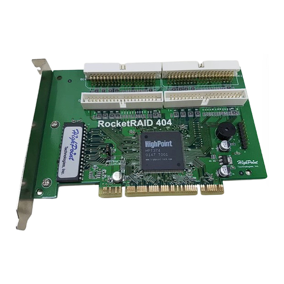
Chapter 2 Adapter Installation This chapter will tell you how to install RocketRAID 404 adapter onto your computer and connect hard disks to the adapter correctly. Please make sure to read this chapter carefully before starting your installation procedures. Contents of this Chapter: 2.1 Adapter Layout... - Page 10 Adapter Installation 2.1 Adapter Layout Adapter Setting of JP1: 1-2 short connected : Disable loading configuration from adapter’s BIOS, and use the default on-chip configuration instead. 2-3 short connected: Enable loading configuration from adapter’s BIOS. The default setting of JP1 is 1-2 short connected. No need to change JP1 setting after you got the adapter.
-
Page 11: Adapter Installation
2. Please discharge static electricity from your body by touching a conductor; 3. Remove the corresponding card bracket from the back of the computer chassis; 4. Insert the RocketRAID 404 adapter steadily into a PCI slot on motherboard and then settle it with screw;... -
Page 12: Verify Adapter's Installation
RocketRAID 404 adapter has been successfully installed and recognized by the computer. Next, RocketRAID 404 adapter’s BIOS will scan the connected hard disks. Please pay attention to the screen display (See next page screen shot). If all connected hard disks are correctly detected out, it indicates that all the hard disks have been connected correctly and recognized by the computer. -
Page 13: Driver Installation
Adapter Installation 2.5 Driver Installation After the RocketRAID 404 adapter is installed and recognized by computer, user can start the installation of driver. Windows 98/Me Installation After Windows 98/Me is start-up, Windows system will automatically find the newly installed adapter and prompt user to install its driver. Follow these steps to install the driver: 1. - Page 14 Adapter Installation 5. After rebooting, Windows will automatically find RCM devices and install its drivers. Verify Installation After the driver installation finished and the computer restarted: 1. Right-click on icon on desktop, and then select item My Computer Properties from the popup menu; 2.
- Page 15 Adapter Installation 2. Within the follow-up window, select item, then click on button; Driver 3. Within the follow-up window, click on Have Disk... button, the following window will appear, see below; 4. Insert the driver diskette, and type in the path of driver location: A:\Win_NT in the above window, then click OK(if users install driver from CD-ROM make sure input the correct path, for example, D:\RR404\Windows\Driver\Win_NT);...
- Page 16 Adapter Installation If there are two HPT374 UDMA/ATA133 RAID Controller items, it indicates that the driver has been successfully installed. Otherwise, if user cannot find these two device items, or there is marks on device icon, it indicates that the driver has not been correctly installed and user need to delete the devices and reinstall the drivers.
- Page 17 6. Next, Windows will find another hardware, please repeat step 1, step 4 and step 5 to operate; 7. Next, Windows will find twice, please confirm the two HighPoint RCM device Digital Signature Not Found windows when they appear, when finished, please restart the computer;...
- Page 18 Adapter Installation items HPT374 UDMA/ATA133 RAID Controller HighPoint RCM Device exists in the popup Device Manager window (see above), it indicates that the driver has been successfully installed. Otherwise, if user cannot find these four device items, or there is...
- Page 19 Adapter Installation Just repeat step 5 and step 6 to finish the driver installation. When finished, please restart the computer. Install driver during Windows XP installation 1. Booting from CD-ROM, when the Windows XP Setup blue screen appears and prompt user to press F6 key to install a third party SCSI or RAID driver, please press...
- Page 20 Adapter Installation items HPT374 UDMA/ATA133 RAID Controller HighPoint RCM Device exist in the pop-up Device Manager window (see above), it indicates that the driver has been successfully installed. Otherwise, if user cannot find these four device items, or there is...
-
Page 21: Bios Configuration
RocketRAID 404 provided on-card BIOS configuration utility, through which, user can configure and manage disks or disk arrays connected to RocketRAID 404 adapter. BIOS configuration utility is specially useful when user wanted to create a disk array before an OS is installed. - Page 22 BIOS Configuration Utility 3.1 Enter BIOS Configuration Utility When the following information appears on screen during the computer is starting, press Ctrl+H key to enter BIOS configuration utility. The main interface of BIOS configuration utility is as below: Main Menu: This column lists all currently available operation commands. This column gives help information about the current selected Help: item and the prompts on available operations.
- Page 23 BIOS Configuration Utility 2. Highlight the and press ENTER, then a list of array modes will Array Mode appear, see below: Just highlight the target array model that you want to create, and then press ENTER to confirm the selection; If user selected RAID 1 (mirror) array, then an option list will popup to enable user selecting will let BIOS reserve...
- Page 24 BIOS Configuration Utility 4. Within the Menu column of main interface, use the arrow key to highlight and press ENTER, the column will be Select Disk Drives Status activated, see below: Just highlight the target disks that you want to use and press ENTER to select them respectively;...
- Page 25 BIOS Configuration Utility Warning: 1. Please pay attention to the warning message at Step 6: Creating RAID 0 array, JBOD array or RAID 0/1 array will destroy all data on all the selected disks. When creating mirror array, Duplication operation will reserve the data on source disk (the firs selected disk) and copy them onto the mirror disk (the second selected disk) when creating mirror array;...
- Page 26 BIOS Configuration Utility 3.4 Add/Delete disks into/from spare pool Follow these steps to add disks into spare pool or delete disks from spare pool: 1. Within the Menu column of main interface, use the arrow key to highlight Create/Delete Spare item and press ENTER, then the Status column will be...
- Page 27 BIOS Configuration Utility Just use the arrow key to highlight the target disk or disk array, then press ENTER to select it as boot device. If user select a disk or disk array which has a boot mark and press ENTER, then its boot setting will be canceled.
- Page 28 BIOS Configuration Utility Just select Duplicate Now to duplicate, or select Continue to Boot to skip. If user select Continue to Boot, user still can duplicate the array after booting into the OS. 3.7 Rebuild Broken RAID 1 or 0/1 array When booting computer, if BIOS detects one member disk of RAID 1 or 0/1 array is failed, the array will be marked as broken status.
- Page 29 BIOS Configuration Utility 1. Power off and replace the failed drive This command enables user to power off the computer and replace the failed disk with a good one. If your computer does not support APM, you must turn off your computer manually. After replacement, user can boot into BIOS and select the to rebuild the broken array.
- Page 30 BIOS Configuration Utility Just highlight the target disk and press ENTER to select it; 2. Then the warning message will appear, see below: Please pay much attention to the warning message, and then press use that disk to rebuild, or press to cancel.
-
Page 31: Installation
Chapter 4 ATA RAID Software This chapter introduces for using HighPoint ATA RAID Management software in detail. Contents of this chapter: 4.1 Installation 4.2 Getting Start 4.3 Configuration Functions 4.4 Management Functions 4.5 View Information 4.6 Rebuild Broken RAID 1 or 0/1 Array... - Page 32 2. Confirm the follow-up dialogue windows to finish the installation; 3. When installation completed, restart the computer; With the default option, the setup program will create program group: Start--> Program-->HighPoint. This program group contains the following items: Main Program HighPoint ATA RAID Management software...
- Page 33 ATA RAID Software The main interface has five tabs: File, Configuration, Management, and Help. View You can switch to different tabs by clicking on it. File: This tab displays welcome information. Click the Exit button to exit ATA RAID software. Configuration: This tab includes four sub-tabs, they are: Create RAID,...
- Page 34 ATA RAID Software Help: This tab contains the help information for this software. 4.3 Configuration Functions Create Disk Array Follow these steps to create a disk array: 1. Click the tab Configuration --> Create Raid, the following window will appear: Within this interface: This drop-down box enable user to select disk array type.
- Page 35 ATA RAID Software This pane will list out all the disks that currently can be Available Disks: used to create disk array. Selected Disks: This pane will list out the disks that have been selected to create the disk array. User can highlight the specific disk pane and click the corresponding hand Available Disks icon to select that disk into the...
- Page 36 ATA RAID Software Warning: 1. Please pay attention to the warning message at Step 2: Creating stripe array, JBOD array or 0/1 array will destroy all the data that already on the selected disks. When creating mirror array, Duplicate operation will reserve the data on source disk (the first selected disk) and copy them onto the mirror disk(the second selected disk);...
- Page 37 ATA RAID Software 2. Highlight the disk array in the Available Array pane, and then click on the corresponding hand icon to add it into the Selected Array pane, then click on button; Delete 3. Next, the warning message will popup, see below: Please pay much attention to the warning message, and just click delete the selected disk array, or click Cancel...
- Page 38 ATA RAID Software Within this interface: All availabe disks that can be added into the spare pool Available Disks: will be listed in this pane. Spare disks will be listed in this pane. Pool: 2. Within the pane, highlight a disk and then click the Available Disks corresponding hand icon to add it into the spare pool, or within the pane...
- Page 39 ATA RAID Software Please pay attention to the warning message, and then click to add/ remove the disk into/from the spare pool, or click to cancel; 4. Restart the computer when completed. Warning: 1. Adding a disk into spare pool will destroy all the data on that disk. Duplicate RAID 1 or 0/1 array When a RAID 1 or 0/1 array is in critical status, software will promt user to duplicate that RAID 1 or 0/1 array.
-
Page 40: Management Functions
ATA RAID Software Within this interface: List: All RAID 1 and 0/1 arrays that can be duplicated will be listed Arrays in this pane. 2. Highlight a disk array within the pane, then the array’s Arrays List information will be shown on the right side (see above picture), then click on button to start duplication, the progress bar will show the Start duplication progress. - Page 41 ATA RAID Software Within this interface: SMTP Server: Type in the domain name or IP address for the SMTP server that you will use to send email. Type in the port of the SMTP service on the email server. Port: Type in the email address where the notification Administrator: information will be sent to.
-
Page 42: View Information
ATA RAID Software 4.5 View Information System View All devices will be shown in this window, including the disk arrays (Logical Devices), the hard disks (physical devices) and the controller. Click the tab --> View, the following window will appear: View System Within this interface, user can perform the following operations:... - Page 43 ATA RAID Software (3) Viewing Physical Device Information Double-click on the hard disk icon that you want to view, then information table about that hard disk will popup as below: (4) Viewing Controller Information Double-click on the controller icon, then the information table about the controller will popup as below: 4-12...
- Page 44 ATA RAID Software Just click the scrolling bar to view all information about the controller. (5) Disk Array Operation Right-click on the disk array icon, from the pop-up menu, you can select to delete or rename the disk array. Note: If the array is being duplicated, broken or disabled, the right-click menu will not be available.
- Page 45 ATA RAID Software Within this interface, user can: (1) Selecting what type of events to be listed There are three types of events: Information, and Error. Just check the Warning information types under the Filter option to select what types of information to be listed.
-
Page 46: Rebuild Broken Raid 1 Or 0/1 Array
ATA RAID Software 4.6 Rebuild Broken RAID 1 or 0/1 Array During the running of ATA RAID software, if a RAID 1 or RAID 0/1 array is broken due to a disk failure, then the software will report the error and warn user with beeping until user confirm the error by clicking the button, like below: If there is a spare disk in the spare pool which can be used to rebuild the broken... - Page 47 ATA RAID Software Then the followup window will appear as below: Just select the broken array, then click OK and confirm the follow-up data loss warning message box to finish the rebuilding of the selected broken array. After rebuilding, the new array will be automatically duplicated to rebuild the lost data. (2) Hot swapping a hard disk to rebuild Follow these steps to rebuild by this way: Hot swap on a good hard disk, then within the ATA RAID software click...
- Page 48 ATA RAID Software Just select the broken array, then click and confirm the followup data loss warning message box to finish the rebuilding of the selected broken array. After rebuilding, the new array will be automatically duplicated to rebuild the lost data. (3) Power off the computer and connect a new hard disk, then power on and boot into BIOS or ATA RAID software to rebuild.
-
Page 49: Trouble Shooting
Chapter 5 Trouble Shooting This chapter will list the most possibly occurred problem and most frequently asked question, and their corresponding solution. Please refer this chapter when you encounter a problem or do not know what to do when using our product. - Page 50 After checked the above points, replace the computer case and power on the computer. 2. The hard disk connected to adapter can not be detected out. After the RocketRAID 404 adapter is recognized, the adapter’s BIOS will start to scan disks connected to the adapter, the information will display as below:...
- Page 51 1. Set SCSI device as the fisrt booting device in main board BIOS; 2. Set a booting device in RocketRAID 404 adapter BIOS (refer Chapter 3 on how to set a boot device); 5. Why Windows found two new hardwares and ask me to install...
-
Page 52: Appendix A Glossary
Appendix A Appendix A Glossary Array Also known as Disk Array, two or more hard disks combined together to appear as a single device to the host computer. Broken Array Disk array with a member disk failed. A broken RAID 1 or 0/1 array can still function with the remained normal disks, but a broken RAID 0 or JBOD will no longer function. - Page 53 Appendix A RAID Levels RAID levels refer to different array architectures (or methods of organizing a disk array). Different RAID levels represent different performance level, security level and cost. RAID 0/1 Mirroring of two striped disk arrays. It is the combination of RAID 0 and RAID 1. Rebuild The ability to use a new disk to replace the failed disk in a redundant disk array (say mirror array or 0/1 array), then to repair the broken disk array and recover all the data...
- Page 54 Read this manual carefully; Visit our website: We will post the most www.highpoint-tech.com updated materials and FAQs onto our website. If you still can not solve the problem after tried the above two ways, please contact our technical support: support@highpoint-tech.com...
Need help?
Do you have a question about the RocketRAID 404 and is the answer not in the manual?
Questions and answers