Table of Contents
Advertisement
Quick Links
Advertisement
Table of Contents

Related Manuals for EnerSys NexSys COMpact


Summary of Contents for EnerSys NexSys COMpact
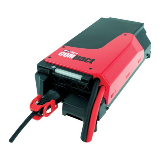
- Page 1 OWNER’S MANUAL www.enersys.com...
-
Page 2: Table Of Contents
CONTENTS Safety Instructions ......4 Aim of this Manual ......4 Labels ..........4 Electrical Safety ......5 CANbus Recommendations ..5 EU Declaration ....... 6 Presentation and Use ....... 6 Introduction ........6 Mechanical Installation ....7 Electrical Connection ....7 Front Panel ........ - Page 3 COMpact battery that may be required by local laws and/or industry standards. Proper instruction and training of all users must be ensured prior to any contact with the battery system. For service, contact your sales representative or call: EnerSys Asia EnerSys EMEA 152 Beach Road EH Europe GmbH...
-
Page 4: Safety Instructions
• Must be used in conformance with its indicated chargers. level of protection and never come into contact with water. When producing this manual, EnerSys has aimed ® • Must be used within the temperature limits to provide its information in as simple and precise stated in the Safety Instructions. -
Page 5: Electrical Safety
It is observed (WEEE 2002/96 EC). strictly forbidden to use inappropriate fuses or EnerSys reserves the right to make any to short-circuit the fuse holders. This equipment improvements and/or modifications to the... -
Page 6: Eu Declaration
SAFETY INSTRUCTIONS EU Declaration EnerSys hereby declares that the • Control of Electromagnetic Fields Regulations chargers in the NexSys COMpact (S.I. 2016/588) ® range covered by this declaration • Directive 2013/35/EU: conform to the descriptions laid down Electromagnetic fields in European and UK Regulations: BS EN IEC 62311: 2020 •... -
Page 7: Presentation And Use
PRESENTATION AND USE Mechanical Installation The charger is designed to be embedded in a battery The charger shall be installed to ensure a free space of compartment inside the forklift (always use genuine 0.1m at both front and back sides. Any action should rubber cushion parts to hold the charger). -
Page 8: Front Panel
PRESENTATION AND USE Front Panel Item Function 1 Function 2 Charger cover Access to the DC cable connections Access to the output fuse Connector covers Access to the peripheral connectors Cover screws (x2) Securing connector covers Rubber cushion (x4) M4 male-female spacers Airflow Direction from back to front side USB port... -
Page 9: Charge
PRESENTATION AND USE Charge Connect the charger to the mains supply. Charge the battery During the charge, the yellow LED lights up. Off-charge display With the charger in waiting mode, the LEDs are 2. Completion of the charging process OFF. When the charger completes the charging process, the green LED is lit. -
Page 10: After The Charge
PRESENTATION AND USE After the Charge Charge history • The charger shall be in stand-by mode The charger records hundreds of items in charge (off-charge) history. An internal clock allows cycle dating. • Connect a USB stick on the charger (with the Downloading charge history is available: firmware to upload) •... -
Page 11: Indication Codes
PRESENTATION AND USE Connectivity (cont.) Technical characteristics: Temperature sensor Max. switching power 62VA The battery temperature can be monitored by Max. switching voltage 100VDC connecting an external sensor to the charger. High Max. switching current 2A temperatures are indicated by activating the buzzer For wire insertion/removal, push the and/or a flashing yellow LED (refer to Fault Codes spring on the connector (orange part). -
Page 12: Fault Codes
PRESENTATION AND USE Fault Codes Flashing Intermittent beeping Green Yellow Buzzer Indication Cause Solution DF1 appears when the charger is not able The charger cannot to supply its output current. DF1* charge the battery. Check the mains supply. Check the charger‘s setting. Check the correct connection of the DF2* Output fault. - Page 13 NOTES...
- Page 14 NOTES...
- Page 15 NOTES...
- Page 16 Subject to technical modification without any prior notice. E.&O.E. © 2024 EnerSys. All rights reserved. Trademarks and logos are the property of EnerSys and its affiliates, except for Bluetooth and CE, which are not the property of EnerSys. Subject to revisions without prior notice. E.&O.E.
Need help?
Do you have a question about the NexSys COMpact and is the answer not in the manual?
Questions and answers