Table of Contents
Advertisement
Quick Links
Advertisement
Table of Contents

Related Manuals for EnerSys NEXSYS TPPL


Summary of Contents for EnerSys NEXSYS TPPL
- Page 1 NEXSYS ® TPPL ATP BATTERY SERVICE MANUAL www.enersys.com...
-
Page 2: Table Of Contents
CONTENTS ATP Battery ........4 ATP Cover .......... 4 Possible Faults/Solution ....5 Blown Fuse ........5 Fan Damage ........7 Mechanical Damage to the Fan ... 9 Damage to Main Power Cable ..10 Cell Replacement ......12 Parts Catalogue ........ 13... - Page 3 Proper instruction and training of all users must be ensured prior to any contact with the battery system. For service, contact your sales representative or call: 1-800-ENERSYS (USA) 1-800-363-7797 www.enersys.com www.experiencenexsys.com Your Safety and the Safety of Others is Very Important...
-
Page 4: Atp Battery
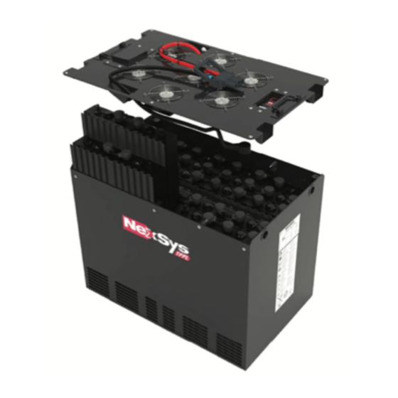
ATP BATTERY & COVER ATP Battery The ATP battery is a new TPPL battery configuration to meet heaviest-duty applications due to active thermal management. This solution differs from a standard TPPL in that the battery is equipped with fans forcing airflow through the battery. The benefit of this solution is translated into higher charge rate acceptance (0.5C5), higher throughput/day (240%) and a longer lifetime compared to a non-ATP... -
Page 5: Possible Faults/Solution
POSSIBLE FAULTS/SOLUTION All repairs must be carried out safely and only when the battery is not connected to a charger! Blown Fuse One or more fans have stopped working. 1. Remove the 4 M6x10 ISO 7380-2 screws securing the fuse cover (Figure 2). 2. - Page 6 POSSIBLE FAULTS/SOLUTION Blown Fuse (cont.) Example: One fan not working. 1. Remove the 4 M6x10 ISO 7380-2 screws securing the fuse cover (Figure 6). 2. Locate the fuse for the non-functioning fan (Figure 7). • Based on Drawing 9936 50008_l7_A (can be downloaded from PSR) for this battery, on the last page we find the number of this fan (Figure 8).
-
Page 7: Fan Damage
POSSIBLE FAULTS/SOLUTION Blown Fuse (cont.) Fan Damage If the fuse is OK after checking, check the continuity of the fan circuit. 1. Disconnect the fan power circuit by opening the fuse. 2. Place the positive test probe in the fuse test hole on the fan side (as in the case of a blown fuse) and the negative test probe in the free slot of the minus bus (Figure 11). - Page 8 POSSIBLE FAULTS/SOLUTION Fan Damage (cont.) 3. Unscrew at least 4 M6x10 ISO 7380-2 screws (the number depends on the size of the battery). 4. Disconnect the harness from the battery (Figure 12). 5. Remove the ATP cover. See cover inside view in Figure 13.
-
Page 9: Mechanical Damage To The Fan
POSSIBLE FAULTS/SOLUTION Fan Damage (cont.) 10. Replace the damaged fan. 11. Strip the insulation from the ends of the fan cables (Figure 17). Stripping length must be from 9 mm minimum to 11 mm maximum. 12. Put everything back together in reverse order. Maintain the correct position of the fan as shown in Figure 18. -
Page 10: Damage To Main Power Cable
POSSIBLE FAULTS/SOLUTION Damage to Main Power Cable Fans don’t work 1. BATTERY SIDE a. Check the main fan power cables from the plug to the fuse box. b. Carry out a visual inspection for mechanical damage to the cables - if is OK, go to point 1.c;... - Page 11 POSSIBLE FAULTS/SOLUTION Damage to Main Power Cable (cont.) 2. CHARGER SIDE a. Carry out a visual inspection of mechanical damage to the cables from the charger side —if you observe damage, replace broken parts. If everything is OK, go to point 2.b.
-
Page 12: Cell Replacement
POSSIBLE FAULTS/SOLUTION Cell Replacement Replace the cell as standard, maintaining the correct positions of the corrugated wedging (DO NOT CHANGE POSITION). -
Page 13: Parts Catalogue
PARTS CATALOGUE Parts Catalogue Part Name Picture Hexagon socket button head screw with flange ISO 7380-2 13191SPEZNM0610 Stainless Steel A2-70 M6x10 Hexalobular countersunk head screw DIN -965 A 13191SPEINM0601 Stainless steel A2-70 M6x12 Screw M4x20 ISO 14580 A2-70 8122034 Nut M4 DIN 985 A2-70 8122042 Screwless end stop WAGO 249-116 8121913... - Page 14 PARTS CATALOGUE Parts Catalogue (cont.) Part Name Picture 2-conductor jumper; 2-way; insulated 8121954 WAGO 2002-402 4-conductor jumper; 2-way; insulated 8121962 WAGO 2001-402 Cable tie: L=180mm, W=4.6mm 8122018 Adhesive base for cable tie up to 4.6mm 8122001 Metal Finger Guard for 120x120mm Fan 8121905 Fan 48V Atex 120*120*38 8121816...
- Page 15 PARTS CATALOGUE Parts Catalogue (cont.) Part Name Picture Cable H07 VK 1x2,5mm2 BLACK 8129106 Number of pillars CAN bus 6LA20743-E1E Wi-iQ4™ 6LA20743-E2E 6LA20743-E3E Content: Wi-iQ3™ with Clamp 6LA20720B-2 2 (70 - 120qmm) 120V Wi-iQ3™ KIT 70-120mm2600A 3766236 BLE-1 120 V Current Sensor 6LA20712 Wi-iQ3™...
- Page 16 © 2024 EnerSys. All rights reserved. Unauthorized distribution prohibited. Trademarks and logos are the property of EnerSys and its affiliates except UL, Android and iOS, which are not the property of EnerSys. Subject to revisions without prior notice. E.&O.E. EMEA-EN-SM-NEX-TPPL-ATP 0424...
Need help?
Do you have a question about the NEXSYS TPPL and is the answer not in the manual?
Questions and answers