Advertisement
Specifications
Listings:
th
o
UL1778 5
Edition, 6/13/2016
nd
UL1741 2
Edition, 1/28/2010 with supplement SA
o
CSA22.2, No. 107.1-01 Ed:3 (R2006)
o
Certifications:
HECO Rule 14 SRD
o
California Rule 21 SRD
o
o
IEEE 1547-2003
IEEE 1547.1-2005
o
System Grounding and Bonding:
In this product, the PV, AC, and battery circuits are
isolated from the enclosure. This product has been
evaluated, listed and identified by UL to meet the
requirements of 690.41 and 250.4(A) of the NEC.
o
The PV system ground reference and protection
is provided internal to the SkyBox, in accordance with
NFPA 70 690.41(A)(6).
o
The AC connections are not bonded to ground.
The usual location for a neutral-ground bond is
at the main AC service panel. Make sure to establish
a neutral-ground bond when installing
in an off-grid application.
o
The battery connection is not bonded to ground.
Make sure to establish a negative-ground bond for
each battery system. An 8½" AWG #4 green wire is
included with the hardware kit for this purpose.
Equipment grounding is required by Section 250 of the
National Electric Code (ANSI/NFPA 70) and Canadian
Electrical Code (C22.1).
Overcurrent Protection
The battery disconnect device in the BOS does not
o
provide overcurrent protection. The installer must
provide protection for the battery circuit according to
the following parameters.
Maximum 175 Adc
Minimum 10 kA AIC
AC overcurrent protection is provided in the BOS.
o
CAUTION:
!
To reduce the risk of fire, connect only to a circuit provided
with a 60 amperes maximum branch-circuit protection in
accordance with the National Electric Code, ANSI/NFPA 70.
IMPORTANT:
Not intended for use with
life support equipment.
Date and Revision
February 2022, Revision C
Trademarks and logos are the property of Alpha Technologies Services, Inc., EnerSys, and its affiliates
unless otherwise noted. Subject to revisions without prior notice. E. & O.E. UL® is the registered
trademark of UL LLC. IEEE® is the registered trademark of The Institute of Electrical and Electronics
900-0195-01-00 REV C ©2018 OutBack Power.
Engineers, Inc. NFPA® is the registered trademark of National Fire Protection Association, Inc.
All Rights Reserved. Do not copy or distribute without permission.
Electrical Specifications
o
Maximum continuous output: 5000 VA @ 45°C
Nominal input and output voltage: 120/240 Vac
o
Nominal frequency: 60 Hz
o
Maximum continuous output current: 24 Aac
o
o
Maximum grid input current: 48 Aac
o
Maximum generator input current: 48 Aac
Maximum PV source voltage: 600 Vdc
o
Operating PV source voltage range: 200 to 600 Vdc
o
o
Maximum PV input current: 20 Adc
o
Maximum PV short-circuit current: 32 Adc
MPPT range: 250 to 600 Vdc
o
A
output: 0.6 A @ 12 Vdc
o
UX
A
relay: 10 A @ 240 Vac, 5 A @ 30 Vdc
o
UX
o
Nominal battery voltage: 48 Vdc
o
Maximum battery input current: 140 Adc
Battery input voltage range: 42 to 60 Vdc
o
Charging output voltage range: 42 to 60 Vdc
o
o
Maximum battery charging current: 100 Adc
Supported Batteries
Lead-acid
o
Specific lithium-ion batteries; see hyperlink for list
o
Environmental Ratings:
o
Environmental Category: Type 3R
o
Maximum Altitude Rating: 10,000 feet
Maximum Ambient Temperature: 60°C
o
Dimensions
:
Height 47.2" (119.9 cm)
o
NOTE:
o
Width 21.0" (53.3 cm)
The QR codes above
lead to the SkyBox
o
Depth 9.4" (23.9 cm)
product page and a list
Weights
:
of lithium-ion batteries
specified for OutBack
Power products.
o
SkyBox: 87.7 lb (39.8 kg)
BOS: 23.6 lb (10.7 kg)
o
Mounting Bracket: 4.6 lb (2.1 kg)
o
Warranty
The warranty for this product can be downloaded from
https://www.outbackpower.com/resources/warranty/procedures
A copy is available by sending a self-addressed envelope to this address:
Contact Information
Mailing
3767 Alpha Way
Address:
Bellingham, WA 98226 USA
Web Site:
www.outbackpower.com
Quick Start Guide
B
6.0"
A
(15.2 cm)
Hole
spacing
16"
(40.5 cm)
Hole spacing
Mounting Bracket
Ensure the mounting surface is strong enough to handle
three times the unit weight. (See the Specifications section.)
Add plywood or other material as necessary to strengthen the surface.
A Locate this horizontal slat at about eye level for easier display viewing.
B Do not place the top of the mounting bracket more than 6' (183 cm) above
l
l
the floor. This ensures that the SkyBox can be easily lifted onto the bracket.
Mark the placement of the bracket according to A and B, keeping in mind the
dimensions in the second drawing. These dimensions (see above*) show the SkyBox
overlap (beyond the bracket) as well as the vertical measurements with respect to A.
They also add the required minimum clearances of 6" (15.2 cm) to SkyBox top and sides.
(This clearance includes the requirements for SkyBoxes in parallel. See Commissioning.)
IMPORTANT:
No lower clearance is shown. In outdoor installations a 36" minimum clearance above the
ground or floor is required. The lower vertical measurement becomes 60.6" (153.9 cm) from A.
Included in Box:
o SkyBox literature
o SkyBox labels
o Battery conductors
o Remote temperature sensor
o Ground bond conductor
o Hardware kit
WARNING: Burn Hazard
The heat sink (at the top rear of the product) may
reach temperatures greater than 70°C. Install this
product so that casual contact does not occur.
WARNING: Fire/Explosion Hazard
Do not place combustible or flammable materials
within 12 feet (3.7 m) of the equipment. This unit
employs mechanical relays and is not ignition-
protected. Fumes or spills from flammable materials
could be ignited by sparks.
WARNING: Personal Injury
Use safe lifting techniques and standard safety
equipment when working with this equipment.
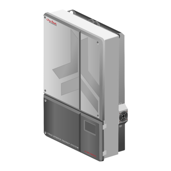
™ True Hybrid Energy System
*
32"
(81.3 cm)
C
28.6"
(72.6 cm)
D
Place the bracket so
that rails C and D are
flush with the surface.
A
This image does not
depict the SkyBox on
the bracket, but the air
24.6"
envelope around the
(62.5 cm)
whole installation
(including clearances).
9.4"
(23.9 cm)
Tools Needed:
o 13 mm socket (torque) wrench
o #2 Phillips (torque) driver
o Flat blade (torque) driver
:
IMPORTANT
This document is for use by qualified personnel familiar with photovoltaic
(PV) systems and maximum power point tracking (MPPT) technology as
well as basic inverter functionality. Users of this document should meet
all local and governmental code requirements for licensing and training
for the installation of electrical power systems with AC and DC voltage
up to 600 volts. This product is only serviceable by qualified personnel.
Clearance and access requirements may vary by location. A 36" (91.4 cm)
clear space in front of the system for access is recommended. Consult
local electric code to confirm clearance and access requirements for the
specific location. If this product is installed or used in a manner other than
specified, the protection it provides may be impaired.
Fuses are not to exceed maximum output rating.
When installed outdoors, use only UL514B-compliant wet location or
rain-tight conduit hubs for entry into the enclosure.
See Specifications for instructions on system grounding and bonding.
NOTE: Additional information on
this product is available at
www.outbackpower.com. For
screen navigation, operation, and
troubleshooting, see the SkyBox
Overview Guide. For programming
and applications, see the SkyBox
Programming Guide.
SkyBox
BOS
(Balance of
System)
1½"
¾"
¾"
¾"
¾"
¾"
¾"
Left
Right
Conduit Knockouts
(Underside of BOS)
o 6 mm Allen wrench
o Digital multimeter (DMM)
Advertisement
Table of Contents

Related Manuals for EnerSys OutBack Power SKYBOX


Summary of Contents for EnerSys OutBack Power SKYBOX
- Page 1 February 2022, Revision C Trademarks and logos are the property of Alpha Technologies Services, Inc., EnerSys, and its affiliates See Specifications for instructions on system grounding and bonding. ...
- Page 2 Mounting Mounting NOTE: The QR codes Place the BOS assembly above lead to videos with on the wall bracket by instructions for unboxing seating the pegs (D) in and mounting the SkyBox. the slots (E). Attach the wall bracket. Center the mounting holes on wall studs.
- Page 3 Wiring COMMUNICATIONS LEGEND NOTE: NOTES The QR code above leads to a video with Make connections in the order indicated. If steps or connections are not applicable, they can be skipped. instructions for wiring the SkyBox. Gen Start (AUX) Tighten the applicable connections to the torque values specified in Table 1.
- Page 4 Wiring Commissioning PV LED Legend NOTES The QR code above leads to a video with instructions for commissioning the SkyBox. BEFORE CLOSING PV DISCONNECT If any onscreen faults or other problems occur during commissioning, see the Troubleshooting section of ...
Need help?
Do you have a question about the OutBack Power SKYBOX and is the answer not in the manual?
Questions and answers