
Related Manuals for EnerSys PowerSafe DDmP


Summary of Contents for EnerSys PowerSafe DDmP
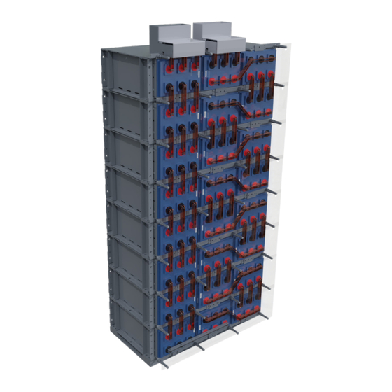
- Page 1 DDmP Battery Safety, Installation, Storage, Operating and Maintenance Manual VRLA Battery System DDmP 125-33 LP Visit us at www.enersys.com...
- Page 2 EnerSys . All rights reserved. 2023 ® This document is proprietary to EnerSys. This document cannot be copied or reproduced in whole or in part, without the express written permission of EnerSys. Please check our website for literature updates. www.enersys.com AMER-EN-IOM-PS-DDmPLP-0223 www.enersys.com...
-
Page 3: General Safety Instructions
The explosion warning symbol is an explosion mark enclosed in a triangle. The explosion warning symbol Explosion is used to indicate locations and conditions where warnings molten, exploding parts may cause serious injury or death if the proper precautions are not observed. AMER-EN-IOM-PS-DDmPLP-0223 www.enersys.com... - Page 4 This includes static electricity from the body. 10. Use proper lifting means when moving batteries and wear all appropriate safety clothing and equipment. 11. Do not dispose of lead acid batteries except through channels in accordance with local, state, and federal regulations. AMER-EN-IOM-PS-DDmPLP-0223 www.enersys.com...
- Page 5 Keep unauthorized personnel away from batteries. Misuse of this equipment could result in human injury and CAUTION equipment damage. In no event will EnerSys be responsible ® or liable for either indirect or consequential damage or injury that may result from the use of this equipment.
- Page 6 AMER-EN-IOM-PS-DDmPLP-0223 www.enersys.com...
-
Page 7: Table Of Contents
5.2. Considerations for Connecting the Battery System to Operating Equipment ......12 5.3. Considerations for Parallel Installation ..................13 6. UNPACKING AND HANDLING FOR INSTALLATION ................. 14 6.1. General ............................14 6.2. Accessories ..........................14 6.3. Recommended Installation Equipment and Supplies ..............15 7. SYSTEM LAYOUT ..........................16 AMER-EN-IOM-PS-DDmPLP-0223 www.enersys.com... - Page 8 MAINTENANCE ............................32 19.1. Battery Cleaning ........................32 19.2. Test Procedures ......................... 34 19.3. Battery Maintenance Reports ....................34 CELL READING ............................. 37 TEMPORARY NON-USE (EXTENDED OUTAGE) ................38 21.1. Installed/Out-of-Service-System ....................38 21.2. Return to Service ........................38 AMER-EN-IOM-PS-DDmPLP-0223 www.enersys.com...
-
Page 9: General Information
1. GENERAL INFORMATION 1.1 . Introduction EnerSys modular valve-regulated lead acid (VRLA) batteries have unique features that make ® them easy to install and maintain. These batteries are composed of absorbed glass mat (AGM) separators with flat plates and electrolyte. -
Page 10: Precautions
® Please call your nearest EnerSys sales/service representative for more information or call the ® corporate office number listed on the back of this manual and ask for EnerSys Energy ® Systems Service. AMER-EN-IOM-PS-DDmPLP-0223... -
Page 11: Safety
YOU NEED TO BE TRAINED IN HANDLING, INSTALLING, OPERATING AND MAINTAINING BATTERIES BEFORE YOU WORK ON ANY BATTERY SYSTEM. You MUST understand the risk of working with batteries and BE PREPARED and EQUIPPED to take the necessary safety precautions. If not, contact EnerSys Energy ®... -
Page 12: Safety Precautions
0.5 kg/5.0 liters of water) on the clothing or material. 3. Apply the solution until bubbling stops, then rinse with clean water. NOTE: In case of an electrolyte SPILL, bicarbonate of soda or an emergency spill kit should be within the battery room. AMER-EN-IOM-PS-DDmPLP-0123 www.enersys.com... -
Page 13: Explosive Gases
Always wear protective clothing and use nonconductive or insulated safety tools when working with ANY battery system. Remove all jewelry that could produce a short circuit. BEFORE working on the system: Disconnect ALL loads and power sources to the battery. Use appropriate lockout/tagout procedures. AMER-EN-IOM-PS-DDmPLP-0223 www.enersys.com... - Page 14 If you have ANY questions concerning safety when working with the battery system, contact your nearest EnerSys sales/service representative to clarify any of ® the noted safety precautions, or call the corporate office number listed on the back of this manual and ask for EnerSys ® Energy Systems Service. AMER-EN-IOM-PS-DDmPLP-0223 www.enersys.com...
-
Page 15: Inspecting The Battery Shipment
Damage to packing material and/or product wetness or stains, indicating electrolyte leakage. If damage is noted: 1. Make a descriptive notation on the delivery receipt before signing. 2. Request an inspection by the carrier. 3. File a damage report. AMER-EN-IOM-PS-DDmPLP-0223 www.enersys.com... -
Page 16: Concealed Damage
REIMBURSEMENT FOR DAMAGES. Refer to the Bill of Lading, if, when performing the parts inventory, you are unsure about the appearance of a part. If you have any questions concerning potential damages, contact your nearest EnerSys ® sales/service representative, or call the corporate office number listed on the back of this manual and ask for EnerSys Energy Systems Service. -
Page 17: Battery Storage Before Installation
6. Maximum total storage time prior to installation is two (2) years from date of shipment from the factory to the customer. Freshening charges are required before the end of the storage time period, or more frequently, as noted in Table 4.1. 7. FAILURE TO CHARGE AS NOTED VOIDS THE BATTERY’S WARRANTY. AMER-EN-IOM-PS-DDmPLP-0223 www.enersys.com... -
Page 18: Advance Preparation
Make every effort to get the battery connected to the charger before expiration of the storage period, thereby avoiding the additional labor cost of freshening charges. WARNING Failure to charge as noted voids the battery’s warranty. AMER-EN-IOM-PS-DDmPLP-0223 www.enersys.com... -
Page 19: Installation Considerations
5. INSTALLATION CONSIDERATIONS 5.1. General If you have any questions concerning the installation considerations, contact your EnerSys ® sales/service representative for clarification or call the corporate office number listed on the back of this manual and ask for EnerSys Energy Systems Service. -
Page 20: Considerations For Connecting The Battery System To Operating Equipment
VRLA batteries may be installed next to electronic Proximity to Electronic equipment unless the equipment generates heat. Equipment EnerSys recommends battery one (1) be at the positive (+) output. ® Cell Identification/ Then label the cells in ascending sequential order as the cells are Numbering connected in series. -
Page 21: Considerations For Parallel Installation
• as short as possible (equal to the longest inter-cell connector). • of equal lengths to the load. • of sufficient ampacity (cable ampacity should not be exceeded). IMPORTANT: EnerSys ® recommends a maximum of 5 parallel strings unless consulted with and approved by EnerSys ® Application Engineering. AMER-EN-IOM-PS-DDmPLP-0223 www.enersys.com... -
Page 22: Unpacking And Handling For Installation
Terminal Plate Kits Terminal Plate Connectors Cell Number Set Labels Assembly Hardware Rack Parts NO-OX-ID Grease for Battery Posts Assembly Drawing Bill of Materials/Packing List Operation & Installation Manual Safety Shields and Standoffs • Miscellaneous: Side Termination Kits AMER-EN-IOM-PS-DDmPLP-0223 www.enersys.com... -
Page 23: Recommended Installation Equipment And Supplies
Wipes, Paper or Cloth Stiff-Bristle Nonmetallic Brush/Pad Tape Measure (Nonmetallic) Safety Equipment and Clothing Small Paintbrush NO-OX-ID Grease CAUTION Be sure you have all the proper protective clothing and safety tools and equipment on hand before starting the installation. AMER-EN-IOM-PS-DDmPLP-0223 www.enersys.com... -
Page 24: System Layout
Floor anchor design (including, but not limited to size, quantity and capacity) and installation are the responsibility of the user/installer – based on applicable codes and regulations. FIGURE 2 Follow the user’s design and the manufacturer’s instructions. AMER-EN-IOM-PS-DDmPLP-0223 www.enersys.com... -
Page 25: Module Assembly And Installation
4 module stack are safety bolted together the lifting equipment can be moved. All module-to-module bolts are to be torqued to 75 ft-lbs. Re-check ALL bolted connections to make sure nothing was loosened during transit. FIGURE 4b AMER-EN-IOM-PS-DDmPLP-0223 www.enersys.com... -
Page 26: Top Bracket
Reinstall terminal safety caps. NOTE: Report any defects to your nearest EnerSys ® sales/service representative for resolution or call the corporate office number listed on the back of this manual and ask for EnerSys Energy Systems Service. ® AMER-EN-IOM-PS-DDmPLP-0223 www.enersys.com... -
Page 27: Module Retainers
See Figure 6. The middle rows use a flat retainer, the top and bottom rows use a retainer with a formed edge. 2. Torque to 20 ft-lbs. 3. Install cells and retainer plates as described until the whole system is full. See Figure 6a. FIGURE 6a AMER-EN-IOM-PS-DDmPLP-0223 www.enersys.com... -
Page 28: Electrical Bonding Instructions
1. Assemble and install the terminal plate FIGURE 8a assembly finger tight as shown in Figure 8, 8a, 9 & 9a. 2. Torque all bolts to 15 ft-lbs. Hand tighten red insulators (cherries). FIGURE 9 FIGURE 9a AMER-EN-IOM-PS-DDmPLP-0223 www.enersys.com... -
Page 29: Connections
3. After all inter-cell connections are completed, torque to 85 in-lbs. FIGURE 10 Secure all connections finger-tight to allow for some adjustment of position. After all inter-cell connections are completed, torque to 85 in-lbs. AMER-EN-IOM-PS-DDmPLP-0223 www.enersys.com... -
Page 30: Terminal Connections
Very light brushing and cleaning with a cloth is generally sufficient. FIGURE 11 2. Apply a light coat of heated NO-OX-ID grease to the terminal bar contact area. 3. Install inter-cell connectors and torque to 85 in-lbs as shown in Figure 11 and 11a. FIGURE 11a AMER-EN-IOM-PS-DDmPLP-0223 www.enersys.com... -
Page 31: Initial System Readings
® representative, or call the corporate office number listed on the back of this manual and ask for EnerSys Reserve Power Service. 4. The Maintenance Report is included at the end of this manual. Measure and record the connection resistance of “CELL to CELL” and “CELL to TERMINAL”... -
Page 32: Terminal Plate Covers And Safety Shields
2. Starting with bottom row, hang safety shields on standoffs as shown in FIGURE 13 Figure 14. NOTE: The bottom of each safety shield will overlap, on the outside, the top of the shield below it. FIGURE 14 AMER-EN-IOM-PS-DDmPLP-0223 www.enersys.com... -
Page 33: Initial And/Or Freshening Charge
Monitor the battery temperature during the charge. If the cell/battery temperature exceeds 105˚F (40˚C) stop the charge immediately and allow the temperature to decrease below 90˚F (32˚C). Failure to follow this warning may result in sever overcharge, damage to the cell/battery, and void warranty. CAUTION AMER-EN-IOM-PS-DDmPLP-0223 www.enersys.com... -
Page 34: Operation
2. The battery becomes fully charged when the current to the battery starts to decrease and stabilize. 3. When the current level remains constant for three consecutive hours, the state-of- charge is approximately 95 to 98%. Full charge can be assumed. For most requirements, the battery is ready for use. AMER-EN-IOM-PS-DDmPLP-0223 www.enersys.com... -
Page 35: Float Operation
AC power interruption or charger failure. Constant voltage output charging equipment is recommended. This type of charger, properly adjusted to the recommended float voltages, and the following recommended surveillance procedures will assist in obtaining consistent serviceability and optimum life. AMER-EN-IOM-PS-DDmPLP-0223 www.enersys.com... -
Page 36: Float Charge Method
Procedure 1, adjust the charger to provide proper voltage as measured at the battery terminals. (When the PowerSafe DDmP125-33 LP Series battery cells are new, expect to see variations in float voltage from cell to cell within a string. These cell voltages should be within ±0.05 volts of the nominal setting). AMER-EN-IOM-PS-DDmPLP-0223 www.enersys.com... -
Page 37: Equalizing Charge
Do NOT equalize PowerSafe DDmP125-33 LP Series battery cells if they are within the following voltage limits: ±0.09 volts of the nominal value, as determined in Section 16.2.1, Procedure No.1. ±0.05 volts of the nominal value, as determined in Section 16.2.1, AFTER ONE YEAR Procedure No.1. AMER-EN-IOM-PS-DDmPLP-0223 www.enersys.com... -
Page 38: Equalizing Charge Method
During charge, if the cell/battery temperature exceeds 105˚F (40˚C) stop the charge immediately and allow the temperature to decrease below 90˚F (32˚C). Failure to follow this warning may result in sever overcharge, damage to the cell/battery, and void warranty. AMER-EN-IOM-PS-DDmPLP-0223 www.enersys.com... -
Page 39: Battery Taps
Do NOT use any type of oil, solvent, detergent, petroleum-based solvent, or ammonia solution to clean the jars or covers. These materials will have an adverse effect and cause permanent damage to the battery jar and cover and will void the warranty. AMER-EN-IOM-PS-DDmPLP-0223 www.enersys.com... - Page 40 Flat Washer d. Battery Terminal f. Flat Washer h. Hex Nut WARNING STAMPED FLAT WASHERS MAY HAVE ONE SHARP EDGE. INSTALL THE WASHER WITH THE SHARP EDGE AWAY FROM THE INTER-CELL CONNECTOR TO AVOID DAMAGING THE PLATING. AMER-EN-IOM-PS-DDmPLP-0223 www.enersys.com...
-
Page 41: Test Procedures
® number listed on the back of this manual and ask for EnerSys Energy Systems Service. Accumulate and permanently record the following data for review by supervisory personnel so that any necessary remedial action may be taken: 1. - Page 42 These internal ohmic measurements, when compared with baseline value or the average value, may indicate the beginning of a problem inside the cell. Then corrective actions can be taken to avoid a battery system failure. EnerSys ®...
- Page 43 BATTERY MAINTENANCE REPORT — DDmP125-33 LP Series...
- Page 44 BATTERY MAINTENANCE REPORT — DDmP125-33 LP Series...
-
Page 45: Cell Reading
20. CELL READING The square post terminal on this product allows for direct access to the terminal when taking cell readings. The diagrams below are meant as a reference guide when taking readings. AMER-EN-IOM-PS-DDmPLP-0223 www.enersys.com... -
Page 46: Temporary Non-Use (Extended Outage)
To return the battery to normal service: Reconnect the battery, the load and charger. If any cells OCV’s are below 2.11 V, give the battery an equalizing charge as described in Section 16.3.1. Return the battery to float operation. AMER-EN-IOM-PS-DDmPLP-0223 www.enersys.com... - Page 47 Reading, PA 19605, USA 6300 Zug Singapore 189721 Tel: +1-610-208-1991 / Switzerland Tel: +65 6508 1780 +1-800-538-3627 ©2023 EnerSys.® All rights reserved. Trademarks and logos are the property of EnerSys and its affiliates unless otherwise noted. Subject to revisions without prior notice. E.&O.E.
Need help?
Do you have a question about the PowerSafe DDmP and is the answer not in the manual?
Questions and answers