
Related Manuals for Microchip Technology BM70


Summary of Contents for Microchip Technology BM70
- Page 1 BM70/71 Bluetooth ® Low Energy Module User’s Guide 2016-2022 Microchip Technology Inc. and its subsidiaries DS50002542C...
- Page 2 Microchip Technology Inc. in other countries. stated. GestIC is a registered trademark of Microchip Technology Germany II GmbH & Co. KG, a subsidiary of Microchip Technology Inc., in other countries. All other trademarks mentioned herein are property of their respective companies.
-
Page 3: Table Of Contents
A.1 BM70 EVB Reference Schematics ............239 B.1 BM71 EVB Reference Schematics ............241 C.1 Quick Reference of Host to BM70/71 Module Commands ......243 C.2 Quick Reference of BM70/71 Module to Host Event Responses ....246 2016-2022 Microchip Technology Inc. DS50002542C-Page 3... - Page 4 ® BM70/71 Bluetooth Low Energy Module User’s Guide 2016-2022 Microchip Technology Inc. DS50002542C-Page 4...
- Page 5 • Document Revision History DOCUMENT LAYOUT This document describes how to use the BM70/71 module, as a development tool to emulate and debug firmware on a target board. This user’s guide is composed of the following chapters: • Chapter 1. “Overview” provides an overview of the BM70/71 module and its features.
- Page 6 ® BM70/71 Bluetooth Low Energy Module User’s Guide • Appendix A. “BM70 EVB Schematics” provides the BM70 EVB reference schematics. • Appendix B. “BM71 EVB Schematics” provides the BM71 EVB reference schematics. • Appendix C. “Commands Summary Quick Reference” provides the quick references of commands used to/from the host and the BM70/71 module.
- Page 7 This is a caution note. box, or when used in a table or figure, it is located at the Note 1: This is a note used in a bottom of the table or figure. table. 2016-2022 Microchip Technology Inc. DS50002542C-Page 7...
- Page 8 BM70/71 Bluetooth Low Energy Module User’s Guide RECOMMENDED READING This user’s guide describes how to use the BM70/71 module. The following Microchip document is available and is recommended as a supplemental reference resource. BM70/71 Data Sheet (DS60001372) Refer to this document for detailed information on the BM70/71 module. Reference information found in this data sheet includes: •...
- Page 9 2-62: Updated the Byte No of Checksum Table 2-64: Updated the Value of Length (L), and OP Code Table 2-67: Updated the Value of Parameter Table 2-171: Added a new row under Parameter (5) 2016-2022 Microchip Technology Inc. DS50002542C-Page 9...
- Page 10 Report Events Figure 2-27: Added Status Report Event Figure 2-69: Replaced with Figure 2-30 • Updated Section 2.3.3.22.4, Section 2.3.3.62.3 and added Section 2.3.3.73 Revision A (October 2016) • Original release of this document 2016-2022 Microchip Technology Inc. DS50002542C-Page 10...
-
Page 11: Chapter 1. Overview
Chapter 1. Overview Microchip’s BM70 and BM71 modules are fully certified Bluetooth Low Energy mod- ules. The BM70 and BM71 modules use Microchip’s IS1870 and IS1871 chips, respec- tively. These chips or Integrated Circuits (IC) include the Bluetooth Low Energy RF transceiver, and a certified Bluetooth Low Energy software stack. - Page 12 Rev 2.0.3 and later to use the new commands and features. With the firmware Rev 2.0.3 and later, the BM70/71 module provides multi-link and multi-role capability under certain configurations.
-
Page 13: Operation Overview
(MCU). In this design, the Bluetooth Low Energy controller and host (which runs the Bluetooth Low Energy stack) are in the IS1870/71 chip on the BM70/71 module. - Page 14 After configuring the BM70/71 module, the host will need to put the module in Application/Run mode, and send commands over the UART interface from the “Com- mand Set”...
- Page 15 Each state handles a specific portion of the overall Bluetooth Low Energy operation. When the host chooses Auto Operation or Manual Operation, the following occurs: • The number of events processed by the BM70/71 module in each state is determined • The way events are generated by the host is determined Auto Operation has a reduced number of events in each state because the available Bluetooth Low Energy functionality is restricted.
- Page 16 The designer of the end target application selects the applicable configuration: Auto Operation or Manual Operation. The designer also determines the available hardware functionality to be used. This complete configuration is programmed into the BM70/71 module by the host. Once configured, the host can switch the module to Run mode and perform the Bluetooth Low Energy operations.
- Page 17 Bluetooth Low Energy protocols, but want the BM70/71 module to act as a virtual UART pipe between the host and the Blue- tooth Low Energy central/master. When Auto Operation is active, any data sent over the UART interface is transmitted to the connected device.
- Page 18 Manual Operation through the “Command Set” protocol. The options listed in Table 1-1 are available when the Auto Operation configuration is chosen. The internal logic of the BM70/71 module executes as a state machine (refer to Section 1.1.2 “System Operation”). Each state has parameters, which can be con-...
- Page 19 The pairing process takes place in this state and, if successful, the BM70/71 module will transition to the Link state. • Link state – In this state the BM70/71 module has an active connection with a Remote Bluetooth Low Energy device. The host can send/receive data to/from the remote device •...
- Page 20 When Auto Operation is active, the Bluetooth Low Energy capabilities of the BM70/71 module are reduced to simplify the operation. The BM70/71 module can only take on the GAP role of the peripheral and, once connected, the module can only become a slave.
- Page 21 Auto Operation, two hardware pins can take on the functionality to indicate the BM70/71 module’s status to the host. The logic level on these two hardware pins can be sampled by the host to gain the Bluetooth Low Energy...
- Page 22 BM70/71 Bluetooth Low Energy Module User’s Guide ® The table below provides the list of the pins in the BM70/71 module which can be con- figured to operate with this functionality. TABLE 1-3: CONFIGURATION OF STATUS INDICATION PINS Functionality BM70 PINS...
- Page 23 When Auto Operation is active, the “Command Set” protocol will be ignored. In order to make changes to some of the features in the BM70/71 module behavior (available in Auto Operation mode), before the module enters the Auto operation mode, a window of time, called the Configuration Timeout, is provided.
- Page 24 BM70/71 Bluetooth Low Energy Module User’s Guide ® FIGURE 1-8: CONFIGURATION TIMEOUT DISABLED 2016-2022 Microchip Technology Inc. DS50002542C-Page 24...
- Page 25 BM70/71 module. If the UART buffer of the BM70/71 module is full, RTS will be raised by the module. If the UART buffer of the host is full, CTS of the module (RTS pins of the host) will be raised by the host. At most two bytes are sent after CTS is raised.
- Page 26 FIGURE 1-10: UART CTS FLOW CONTROL FIGURE 1-11: UART RTS FLOW CONTROL...
- Page 27 1.1.2.1.5 Auto Operation – Pairing Key When the BM70/71 module is connected to a remote device and in the Link state, the host can use the pairing key to force the module to disconnect the link and go back to the Standby state.
- Page 28 RF activity and then the UART is disabled. The module will remain in this state until a power loss event or the host wakes the BM70/71 module. The figure below illustrates how the host can use this functionality.
- Page 29 1.1.2.1.7 Auto Operation – Low Battery Indication Because the host cannot get a status from the BM70/71 module regarding the battery voltage level over the UART, the host can configure the module to use a hardware pin to indicate when certain voltage thresholds have been detected on the BAT_IN pin of the module.
- Page 30 1.1.2.1.8 Auto Operation – Link Quality Indication The BM70/71 module indicates the quality of the RF link by providing a number referred to as the RSSI value. When Auto Operation is active, the host cannot retrieve this num- ber because the UART interface becomes a data pipe and all “Command Set” protocol messages are ignored.
- Page 31 (i.e, Radio) is operating. This information is useful if the host needs to know whether the BM70/71 module is in any of the low-power modes. When Auto Operation is active, the host cannot retrieve this information using the “Status Report”...
- Page 32 The table below provides the possible configuration ranges the host can set the BM70/71 module to. TABLE 1-11: BM70/71 CONFIGURATION RANGE Functionality Parameter Range Parameter Value BM70/71 Active Indication 0x00-0x01 Disabled/Enabled Activity Indication Type 0x00-0x01 RF, Physical Layer Only / RF, Physical Layer + MCU 2016-2022 Microchip Technology Inc. DS50002542C-Page 32...
- Page 33 To exchange data over Bluetooth Low Energy, devices must have the capability of find- ing each other first. When Auto Operation is active, the BM70/71 module can only take on the role of a peripheral (defined in the GAP layer), and a peripheral makes its pres- ence known by following certain rules in Bluetooth Low Energy.
- Page 34 Table 1-13). • Standby Time – This is the total period of time the BM70/71 module will advertise. This value is used after RST_N hardware of a Power-on Reset (POR) event to determine how long the BM70/71 module will advertise in the Standby state.
- Page 35 When Auto Operation is active, the BM70/71 module can only take on the role of a peripheral device (if this behavior is too restrictive, refer to Section 1.1.2.2 “Manual...
- Page 36 This does not mean that the central/master device will accept this request. When this parameter update request is sent, it is based on the internal logic of the BM70/71 module and the host does not have control over this in Auto Operation.
- Page 37 Set_Adv_Enable(0x1C) command is sent by the host. This allows the BM70/71 module to stay in the Standby state but to enter into Broadcast mode sending advertising packets until the host commands otherwise. If the...
- Page 38 BM70/71 Bluetooth Low Energy Module User’s Guide ® The table below provides the different states and applicable modes of the BM70/71 module state machine. TABLE 1-15: STATES AND APPLICABLE MODES OF THE BM70/71 MODULE BM70/71 State Modes Standby state Low-power...
- Page 39 1.1.2.2.1 Manual Operation – General I/O The BM70/71 module has a number of general I/O pins that can be used by the host as digital input/output. These pins can be used as long as they have not been configured for another function during Configuration mode. When a pin is used as an output, the host can drive the pin to a logic level of “1”...
- Page 40 This gives the host additional flexibility to sample voltage levels on the pins through the BM70/71 module. This can be an advantage if the host pin count is limited or if there is a need to combine the logic to reduce the Bill of Material's cost.
- Page 41 The rate at which the timer increments the counter is based on the timer's clock source. The BM70/71 module has three clocks and the host can choose from 32 kHz, 1 MHz, and 16 MHz. The amount of the time taken for the timer to increment the counter until it equals the compare value, or until it reaches the top of its range, is directly related to the speed of the clock.
- Page 42 The Bluetooth Low Energy specification has adopted many different types of service and profile specifications. The BM70/71 module has the support for many of these pub- lic services as well as allowing a user to define proprietary services. During Configura- tion mode, the host can choose the type of services that will be available in Run mode.
- Page 43 The BM70/71 module follows these rules, but this requires memory to store and organize the data (attributes) in a service. The BM70/71 module has an inter- nal memory limitation regarding the amount of addressable information (attributes) for ...
- Page 44 The structure of an attribute does not necessarily define a size for the Permissions field. This is a vendor-specific chosen value. For the attributes in the BM70/71 module, it takes one byte to hold the permission value. 2016-2022 Microchip Technology Inc.
- Page 45 LED by driving the LED off, toggling, or on. Because the BM70/71 module only drives an LED on one hardware pin, the host must choose a unique pattern for each function so the function can be visually detected.
- Page 46 Only used when “Auto Operation is active” (see Shutdown Time Section 1.1.2.1 “Auto Operation”) The table below provides the details of the pins used for LED Indication functionality. TABLE 1-24: PINS FOR LED INDICATION Functionality BM70 Pins BM71 Pins LED0 2016-2022 Microchip Technology Inc. DS50002542C-Page 46...
- Page 47 There are two modes the host can make use of in the BM70/71 module to reduce the overall power. However, they will affect the BM70/71 module behavior, so understating what is affected is important for correct host operation.
- Page 48 Operation – Dis- Timeout coverability”, LINK_DROP Section 1.1.2.1.6 “Aut WAKEUP_PIN o Operation – Link UART_RX_IND Drop”, Section 1.1.2.3.3 “Gen eral Operation – Wake-Up Indication” Section 1.1.2.3.5 “Gen eral Operation – UART Receive Indica- tion” 2016-2022 Microchip Technology Inc. DS50002542C-Page 48...
- Page 49 If enabled, the host can drive this pin to a logic level of “0” to wake-up the BM70/71 module. If the host has disabled the wake-up function and the module enters the Shut- down state, the only way out of this state is with a power cycle or hardware reset.
- Page 50 This signal is available when Manual Operation or Auto Operation is active. As a way to synchronize commu- nication after the signal is driven by the BM70/71 module, the host can configure the BM70/71 module to wait for a predefined time period (T WAIT_WAKEUP_HOST_TIME before sending any UART traffic.
- Page 51 “Reduced Current Consumption” mode is enabled or disabled based on whether this pin is enabled or disabled. The host drives this pin to a logic level of “0” to make the BM70/71 module active and capable of receiving UART data. Doing this effectively terminates the “Reduced Current Consumption”...
- Page 52 TABLE 1-31: PINS FOR UART RECEIVE INDICATION Functionality BM70 PINS BM71 PINS UART_RX_IND P00 (if CTS is disabled) P00 (if CTS is disabled) P36 (if RTS is disabled) P36 (if RTS is disabled) 2016-2022 Microchip Technology Inc. DS50002542C-Page 52...
- Page 53 Therefore, the security level of the encryption is determined by the method of pairing performed. To make use of the “LE Security Mode 1” support in the BM70/71 module, the host MCU needs to configure the I/O capabilities of the accessory. This, together with the capabilities of the peer device, will determine the pairing method and the level of security applied to the connection.
- Page 54 The table below provides the reference for determining the pairing method based on the I/O capabilities of the two devices involved and the role each device plays in the process. TABLE 1-32: REFERENCE FOR DETERMINING PAIRING METHOD Initiator I/O Capabilities DisplayOnly Display Keyboard...
- Page 55 As stated earlier, each pairing method gives the connection a certain level of security and in “LE Security Mode 1”, which is supported in the BM70/71 module, there are four levels of security. The security levels describe the type of security the current connection has or will have, which are: •...
- Page 56 The two figures below illustrate the commands sent by the host MCU to the BM70/71 module based on the “Passkey” method with the BM70/71 module being a Initiator or Responder.
- Page 57 Overview FIGURE 1-28: BM70/71 AS INITIATOR IN PASSKEY METHOD FIGURE 1-29: BM70/71 AS RESPONDER IN PASSKEY METHOD 2016-2022 Microchip Technology Inc. DS50002542C-Page 57...
- Page 58 Setting “pairing not supported”, this results in an unauthenticated unen- crypted level of security for current connection) 0x01 – Pairing Enabled (BM70/71 module will inform peer device, BM70/71 module supports pairing) 0x02 – Pairing Enabled, Authentication Required (BM70/71 module informs peer device pairing supported and needs to result in a...
- Page 59 For Manual Operation Only Pairing_Request(0x42) control pair- ing procedure when BM70/71 module is initiator The use of the following “Command Set” messages, is based on the role BM70/71 module is playing (initiator or responder) BM70/71 module to host “Command Set” messages: Passkey_Entry_Req(0x60)
- Page 60 BM70/71 Bluetooth Low Energy Module User’s Guide ® NOTES: 2016-2022 Microchip Technology Inc. DS50002542C-Page 60...
-
Page 61: Chapter 2. Operating Modes, Configuration And Control
HARDWARE INTERFACE A minimum set of hardware connections is required to interface a host to the BM70/71 module. The figure below illustrates the minimum connections required by the relevant hardware pins on the module. Making these hardware connections between the host and the BM70/71 module will allow a host to control the behavior of the module. -
Page 62: Bm70/71 Mode Selection
At a high level, the test, configuration, and programming modes are entered when the P2_0 pin is latched by the BM70/71 module at logic level ‘0’. The application or run mode, where general Bluetooth Low Energy operation is available, is entered when P2_0 pin is latched by the BM70/71 module at logic level ‘1’. - Page 63 Once a designer implements the necessary signals to allow communication with the end target application's host, the applicable protocols (based on the mode of the BM70/71 module) must be referenced in later sections to learn how to control the behavior of the module.
-
Page 64: Command Set Protocol
Section 1.1.2.2 “Manual Operation”), the “Command Set” protocol is used by the host to control the behavior of the BM70/71 module. This protocol loosely follows the Host Command Interface (HCI) logic flow defined in the Bluetooth Low Energy specifi- cation. If a user is already familiar with the HCI logic flow, understanding this protocol will be straightforward. - Page 65 • Flow control (configurable in some cases, disabled in all other configurations) The baud rate is configurable and is set when the BM70/71 module is in configuration mode. Once set, the BM70/71 module will use this baud rate for all “Command Set”...
- Page 66 In general, all the messages from the host to the BM70/71 module will have some type of response, but not all messages from the module to the host necessarily require previous input (status message events).
- Page 67 When the host is waiting for a response, implement the timeout logic in case of errant operation of the BM70/71 module. This timeout logic period can vary based on the types of messages the host sends to the BM70/71 module. For commands which...
- Page 68 ® READ LOCAL INFORMATION (OPCODE - 0X01) 2.3.3.1 This command is sent from the host to the BM70/71 module to retrieve: • The internal firmware version of the module in Binary Coded Decimal (BCD) format • The Bluetooth address of the BM70/71 module •...
- Page 69 The length of this message changes based on the firmware version of the device. BM70/71 modules with firmware version 106 or later will respond with the sili- con identification value in the message. BM70/71 modules with firmware version 105 or earlier will be included in the silicon identification value.
- Page 70 This command performs a reset on the BM70/71 module. When this command is issued, the behavior of the BM70/71 module is same as when the hardware RST_N pin is used. Internally this command returns the BM70/71 module to “Idle mode” in the Standby state, which is indicated in the response.
- Page 71 This command is only available in Manual Operation. 2.3.3.3 READ BM70/71 STATUS (OPCODE - 0X03) This command is used to read the internal status of the BM70/71 module. This com- mand cannot be used in the Shutdown state because the BM70/71 module is inactive. 2.3.3.3.1...
- Page 72 The BM70/71 module will respond to this command with a Status Report Event (0x81) response. The value in the status will indicate the mode (temporary sub-state) of the BM70/71 module. The BM70/71 module has a total of nine modes. All modes do not apply to all states within the BM70/71 module.
- Page 73 This command is used to read the voltage present on the applicable analog pin/chan- nel. The pin has to be configured appropriately, and some of the channel numbers in the command do not apply to the BM70/71 module because the pin is not available (see Section 1.1.2.2.2 “Manual Operation – Analog Pins”).
- Page 74 (step size) will follow. The step size is based on an internal formula that the host cannot control (for more information, refer to Section 1.1.2.2.2 “Manual Operation – Analog Pins”). The table below provides details of the response format from the BM70/71 module to the host. TABLE 2-13: RESPONSE FORMAT, BM70/71 MODULE TO HOST...
- Page 75 2.3.3.5 INTO SHUTDOWN MODE (OPCODE - 0X05) This command is sent from the host to the BM70/71 module to put the BM70/71 module into Shutdown mode. This will put the BM70/71 module into the “Deep-sleep/Shut- down” low-power mode, which is the lowest current consumption mode for the BM70/71 module.
- Page 76 2.3.3.5.4 Response Format, BM70/71 Module to Host The BM70/71 module will respond with two replies to the host when receiving the Shut- down command. The BM70/71 module will send a Command Complete Event (0x80) response on successfully receiving the message and processing it. The...
- Page 77 This command is only available in firmware Rev 2.0.3 and later. 2.3.3.6.1 Command Format, Host to BM70/71 Module The table below provides details of the command format from the host to the BM70/71 module. TABLE 2-19: COMMAND FORMAT, HOST TO BM70/71 MODULE...
- Page 78 Defaults This does not apply to this command. 2.3.3.6.3 Example The figure below illustrates an example of the Debug (0x06) command from the host to the BM70/71 module. FIGURE 2-10: SEQUENCE DIAGRAM OF DEBUG COMMAND Host BM70/71 Debug command (0x06)
- Page 79 2.3.3.7 READ DEVICE NAME (OPCODE - 0X07) This command is used by the host to read the device name fragment in the BM70/71. During configuration this value can be programmed by the host or by using the Write Device Name(0x08) command.
- Page 80 2.3.3.7.4 Response Format, BM70/71 Module to Host The BM70/71 replies to the host with the Command Complete Event(0x80) response, with the device name added to the parameter field of this event message. The device name is limited to the length allowed in Configuration mode.
- Page 81 2.3.3.8 WRITE DEVICE NAME (OPCODE - 0X08) This command is used to assign a name to the BM70/71 module. This name will be seen by remote devices performing a scan. This command can only be sent from “Idle mode” while in the Standby state.
- Page 82 This command is used to erase all saved Long Term Keys (LTK) from the pairing pro- cess. This list of keys is a list of the remote devices the BM70/71 module has bonded with. This command can only be sent while the BM70/71 module is in “Idle mode” or the “Configuration Window”...
- Page 83 This command is used by the host to find out the settings of the current I/O capabilities of the BM70/71 module. The value returned has an overall impact on the level of security achieved when the pairing process is complete (refer to Section 1.1.2.3.6 “General Operation -...
- Page 84 FIGURE 2-14: SEQUENCE DIAGRAM OF READ PAIRING MODE 2.3.3.10.4 Response Format, BM70/71 Module to Host The BM70/71 module returns the Command Complete Event(0x80) response with the value of the current I/O capability added in the parameters field of this event message.
- Page 85 2.3.3.11 WRITE PAIRING MODE SETTING (OPCODE - 0X0B) This command is used to write the I/O capability of the host into the BM70/71 module. The written value has an overall impact on the level of security the connection will have after the pairing process is completed (refer to Section 1.1.2.3.6 “General Operation...
- Page 86 This command is used to read the bonded (part of the pairing process) device list of the BM70/71 module. The BM70/71 module can only store up to the last eight devices that have bonded. When bonding occurs, the LTK is exchanged and saved.
- Page 87 The BM70/71 module returns the Command Complete Event(0x80) response with the pairing and bonding list added to the parameters field of the event message. The total length is dependent on how many devices the BM70/71 module has stored. The table below provides details of the Command Complete Event(0x80) response format from the BM70/71 module to the host.
- Page 88 Paired and Bonded device Bluetooth address 2.3.3.12.5 Applicable Configuration This command can be used in Manual Operation when the BM70/71 module is in “Idle mode” in the Standby state, and in Auto Operation only when the “Configuration Window” is active.
- Page 89 (opcode - 0x80)”. 2.3.3.13.5 Applicable Configuration This command applies to Manual Operation when the BM70/71 module is in “Idle mode” in the Standby state and to Auto Operation only when the “Configuration Window” is active. 2016-2022 Microchip Technology Inc.
- Page 90 There are four ports (Port 0 to Port 3) with eight general I/O pins each available for control on the BM70/71 module. A port pin is referred to by a combination of the port number and port pin (for example, Port 0 pin 1, is P0_1). Valid pins numbers are zero through seven (0-7).
- Page 91 Event(0x80) response. The value of each port’s (Port 0 to Port 3) digital I/O enable control register is returned. The BM70/71 module returns the digital value read on each port pin, regardless of what the pin has been configured for. These values are added to the parameters field of the event response.
- Page 92 2.3.3.15 PWM CONTROL (OPCODE - 0X0F) This command is used by the host to control the PWM output function on the BM70/71 module. The pins selected for the available PWM channel must not be configured for any other function. For an overview of PWM functionality, refer to Section 1.1.2.2.3 “Manual Operation –...
- Page 93 0x01 – Inverse output 2.3.3.15.2 Defaults This does not apply to this command. 2.3.3.15.3 Example The figure below illustrates an example of PWM control from the host to the BM70/71 module. FIGURE 2-19: SEQUENCE DIAGRAM OF PWM CONTROL 2016-2022 Microchip Technology Inc.
- Page 94 LE Connection Complete Event(0x71) response. This command is only valid while the devices are connected. 2.3.3.16.1 Command Format, Host to BM70/71 Module The table below provides details of the command format from the host to the BM70/71 module. TABLE 2-45:...
- Page 95 The data written can be up to 31 bytes in length, and there is no limitation to the type of data that can be written. 2.3.3.17.1 Command Format, Host to BM70/71 Module The table below provides details of the command format from the host to the BM70/71 module. TABLE 2-48:...
- Page 96 SEQUENCE DIAGRAM OF WRITE ADVERTISING DATA 2.3.3.17.4 Response Format, BM70/71 Module to Host The BM70/71 module returns the Command Complete Event(0x80) response and does not append the additional data to the event response. For more information on format of response, refer to Section 2.3.3.65 “Command Complete Event (opcode -...
- Page 97 If it requests, the scan request packet is only sent to the remote device. 2.3.3.18.1 Command Format, Host to BM70/71 Module The table below provides details of the command format from the host to the BM70/71 module. TABLE 2-50:...
- Page 98 This command is used to setup the advertising parameters of the BM70/71 module. This command can only be sent by the host while the BM70/71 module is in “Idle mode” in the Standby state. For directed advertising, the Bluetooth address can be public or random.
- Page 99 Connectable undirected advertising 1 byte 0x01 Connectable directed advertising 0x02 Scannable undirected advertising 0x03 Non connectable undirected advertising. Setting this value puts the BM70/71 module into broadcast mode 0x04 Proprietary beacon setting Value of Parameter (7) 0x00 Public Device Address 1 byte...
- Page 100 Note: This command is only available in firmware Rev 2.0.3 and later. 2.3.3.20.1 Command Format, Host to BM70/71 Module The table below provides details of the command format from the host to the BM70/71 module. TABLE 2-54: COMMAND FORMAT, HOST TO BM70/71 MODULE...
- Page 101 Value of Parameter (7) 0xXXXX Supervision timeout for the BLE connection. 2 bytes Range: 0x000A to 0x0C80 Time: N*10 msec Time range: 100 msec to 32 seconds 2.3.3.20.2 Defaults This does not apply to this event. 2016-2022 Microchip Technology Inc. DS50002542C-Page 101...
- Page 102 2.3.3.21 SET SCAN PARAMETERS (OPCODE - 0X15) This command is used by the host to set up the scan parameters of the BM70/71 mod- ule. This command is only valid when the BM70/71 module is in “Idle mode” in the Standby state.
- Page 103 Operating Modes, Configuration and Control 2.3.3.21.1 Command Format, Host to BM70/71 Module The table below provides details of the command format from the host to the BM70/71 module. TABLE 2-58: COMMAND FORMAT, HOST TO BM70/71 MODULE Start Length (H) Length (L)
- Page 104 When performing this, it will cause the BM70/71 module to start or terminate the discovery procedure as defined by the Bluetooth Low Energy specification. 2.3.3.22.1 Command Format, Host to BM70/71 Module The table below provides details of the command format from the host to the BM70/71 module. TABLE 2-60:...
- Page 105 Complete Event(0x80) response when it has processed the command from the host. After the Status Report Event (0x81) and Command Complete Event (0x80), the BM70/71 starts sending the results of the advertising scan with the Advertising Report event (0x70). This command does not append additional data to the Command Com- plete Event (0x80) response.
- Page 106 2.3.3.23 LE CREATE CONNECTION (OPCODE - 0X17) This command is used by the host to have the BM70/71 module initiate a connection with a remote device detected during the discovery procedure. For the Bluetooth address parameter in this command, the address of the peer device can be public or random.
- Page 107 This command can only be issued by the host after the LE Create Connection (0x17) command has been issued. 2.3.3.24.1 Command Format, Host to BM70/71 Module The table below provides details of the command format from the host to the BM70/71 module. TABLE 2-64:...
- Page 108 CONNECTION PARAMETER UPDATE REQUEST (OPCODE - 0X19) This command is sent by the host to the BM70/71 module to change the connection parameters of the active link. This command is only valid while the Bluetooth link is successfully established between the BM70/71 module and the peer device.
- Page 109 Range - 0x0006 (7.5 ms) - 0x0C80 (4s) Interval = value * 1.25 ms Parameter 5 is MSB Parameter 6 is LSB 2.3.3.25.2 Default This does not apply to this command. 2016-2022 Microchip Technology Inc. DS50002542C-Page 109...
- Page 110 This command is used to terminate a connection after the link has been established between the BM70/71 module and a peer device. 2.3.3.26.1 Command Format, Host to BM70/71 Module The table below provides details of the command format from the host to the BM70/71 module. TABLE 2-67:...
- Page 111 2.3.3.27 SET ADVERTISING ENABLE_DISABLE (OPCODE - 0X1C) This command is sent by the host to start or stop the BM70/71 module from sending advertising packets. To enable the BM70/71 module to send advertising packets, the module must be in “Idle mode” of the Standby state. The command Set Advertis- ing Parameter(0x13) will determine the type of advertising packets sent by the BM70/71 module.
- Page 112 BM70/71 Bluetooth Low Energy Module User’s Guide ® 2.3.3.27.1 Command Format, Host to BM70/71 Module The table below provides details of the command format from the host to the BM70/71 module. TABLE 2-68: COMMAND FORMAT, HOST TO BM70/71 MODULE Start...
- Page 113 Operating Modes, Configuration and Control 2.3.3.27.3 Example The two figures below illustrate examples of setting advertising packets from the host to the BM70/71 module in Idle mode and Standby mode. FIGURE 2-31: SEQUENCE DIAGRAM OF SET ADVERTISING PACKETS - IDLE MODE...
- Page 114 Status Report(0x03) to discover the state of the BM70/71 module to confirm if the connection is active. 2.3.3.28.1 Command Format, Host to BM70/71 Module The table below provides details of the command format from the host to the BM70/71 module. TABLE 2-70:...
- Page 115 SEQUENCE DIAGRAM OF READ REMOTE DEVICE NAME 2.3.3.28.4 Response Format, BM70/71 Module to Host The BM70/71 module returns the Command Complete Event(0x80) response and adds the received device name from the peer device in the parameters field. For more information on the base format and values, refer to Section 2.3.3.65 “Command...
- Page 116 2.3.3.29 PREPARE WRITE REQUEST (OPCODE - 0X20) This command is used by the BM70/71 when it is acting as the client to request the server to Prepare Write a Characteristic Value of the attribute. The server will respond to this request with a Prepare Write Response, so that the client can verify that the value is received correctly.
- Page 117 2.3.3.30 EXECUTE WRITE REQUEST (OPCODE - 0X21) This command by the client (BM70/71 modules) is used to request the server (peer device) to write or cancel the write of all the prepared values currently held in the pre- pare queue from the client (BM70/71). This command is valid while the Bluetooth link is successfully established between BLEDK3 and the remote host.
- Page 118 BM70/71 Bluetooth Low Energy Module User’s Guide ® 2.3.3.30.1 Command Format, Host to BM70/71 Module The table below provides details of the command format from the host to the BM70/71 module. TABLE 2-78: COMMAND FORMAT, HOST TO BM70/71 MODULE Start...
- Page 119 READ BLOB REQUEST (OPCODE - 0X22) This command is sent by the client (BM70/71) to request the server (peer device) to read part of the value of an attribute at a given offset and return a specific part of the value in a Read Blob Request.
- Page 120 Command complete event(s) (0x80) Ready to receive command 2.3.3.31.4 Response Format, BM70/71 Module to Host The BM70/71 responds to the Read Blob Request command with a response format as described in the table below. TABLE 2-84: RESPONSE FORMAT, BM70/71 MODULE TO HOST...
- Page 121 2.3.3.32 SEND HANDLE VALUE CONFIRMATION (OPCODE - 0X2D) This command is sent by the host MCU via the client (BM70/71) to inform the server (peer device) of the value of an attribute at a given offset as part of the Read Blob .
- Page 122 2.3.3.33 GATT CLIENT – DISCOVER ALL PRIMARY SERVICES (OPCODE - 0X30) This command is used by the host to have the BM70/71 module (client) discover all primary services on a peer device (server). 2016-2022 Microchip Technology Inc. DS50002542C-Page 122...
- Page 123 Operating Modes, Configuration and Control 2.3.3.33.1 Command Format, Host to BM70/71 Module The table below provides details of the command format from the host to the BM70/71 module. TABLE 2-90: COMMAND FORMAT, HOST TO BM70/71 MODULE Start Length (H) Length (L)
- Page 124 (server) when only the UUID service value is known. 2.3.3.34.1 Command Format, Host to BM70/71 Module The table below provides details of the command format from the host to the BM70/71 module. TABLE 2-92:...
- Page 125 This command is only available in Manual Operation. 2.3.3.35 READ CHARACTERISTIC VALUE (OPCODE - 0X32) This command is used by the host to have the BM70/71 module read the “Characteristic value” attribute from a peer device (server). 2016-2022 Microchip Technology Inc.
- Page 126 BM70/71 Bluetooth Low Energy Module User’s Guide ® 2.3.3.35.1 Command Format, Host to BM70/71 Module The table below provides details of the command format from the host to the BM70/71 module. TABLE 2-94: COMMAND FORMAT, HOST TO BM70/71 MODULE Start...
- Page 127 GATT CLIENT - READ USING CHARACTERISTIC UUID (OPCODE - 0X33) This command is used by the host to have the BM70/71 module (client) read the “Characteristic value” attribute from a peer device (server) when only the characteristic UUID is known.
- Page 128 UUID 2.3.3.36.4 Response Format, BM70/71 Module to Host The BM70/71 module returns the Command Complete Event(0x80) response, and adds the handle and the value from the “Characteristic value” attribute in the parame- ters field. For more information on the base format and values, refer to Section 2.3.3.65 “Command Complete Event (opcode -...
- Page 129 2.3.3.37 GATT CLIENT - WRITE CHARACTERISTIC VALUE (OPCODE - 0X34) This command is used by a host to have the BM70/71 module (client) write a value to the “Characteristic value” attribute of a peer device (server). 2.3.3.37.1 Command Format, Host to BM70/71 Module The table below provides details of the command format from the host to the BM70/71 module.
- Page 130 Length Value of Parameter (4) 0xXX Connection Handle of current connection. 1 byte This value was returned by the BM70/71 module in a LE Connect Complete Event(0x71) response Value of Parameter (5) 0x00 Write without Response. The client issues a 1 byte “Write Command”...
- Page 131 GATT CLIENT – ENABLE TRANSPARENT UART SERVICE (OPCODE - 0X35) This command is used by a host to have the BM70/71 module (client) write a value to the “Characteristic value” attribute of a peer device (server). 2.3.3.38.1 Command Format, Host to BM70/71 Module The table below provides details of the command format from the host to the BM70/71 module.
- Page 132 This command is only available in firmware Rev 2.0.3 and later. 2.3.3.39.1 Command Format, Host to BM70/71 Module The table below provides details of the command format from the host to the BM70/71 module. TABLE 2-106: COMMAND FORMAT, HOST TO BM70/71 MODULE...
- Page 133 2.3.3.39.2 Default This does not apply to this command. 2.3.3.39.3 Example The figure below illustrates an example of the Send Prepare Write Response (0x28) command from the host to the BM70/71 module. FIGURE 2-44: SEQUENCE DIAGRAM OF SEND PREPARE WRITE RESPONSE...
- Page 134 This command is only available in firmware Rev 2.0.3 and later. 2.3.3.40.1 Command Format, Host to BM70/71 Module The table below provides details of the command format from the host to the BM70/71 module. TABLE 2-110: COMMAND FORMAT, HOST TO BM70/71 MODULE...
- Page 135 Command complete event(s) (0x80) Ready to receive command 2.3.3.40.4 Response Format, BM70/71 Module to Host The BM70/71 responds to the Send Execute Write Response command with a response format as described in the table below. TABLE 2-112: RESPONSE FORMAT, BM70/71 MODULE TO HOST...
- Page 136 BM70/71 Bluetooth Low Energy Module User’s Guide ® 2.3.3.41.1 Command Format, Host to BM70/71 Module The table below provides details of the command format from the host to the BM70/71 module. TABLE 2-114: COMMAND FORMAT, HOST TO BM70/71 MODULE Start...
- Page 137 This command is only available in firmware Rev 2.0.3 and later. 2.3.3.42.1 Command Format, Host to BM70/71 Module The table below provides details of the command format from the host to the BM70/71 module. TABLE 2-118: COMMAND FORMAT, HOST TO BM70/71 MODULE...
- Page 138 0x0C: Insufficient encryption key size 0x0D: Invalid attribute value length 0x0E: Unlikely error 0x0F: Insufficient encryption 0x10: Unsupported group type 0x11: Insufficient resources 0x80: Application error 2.3.3.42.2 Default This does not apply to this command. 2016-2022 Microchip Technology Inc. DS50002542C-Page 138...
- Page 139 Table 2-175 2.3.3.43 GATT SERVER – SEND CHARACTERISTIC VALUE (OPCODE - 0X38) This command is used by the host to have the BM70/71 module (server) send a “Characteristic value” to a peer device (client). 2016-2022 Microchip Technology Inc. DS50002542C-Page 139...
- Page 140 BM70/71 Bluetooth Low Energy Module User’s Guide ® 2.3.3.43.1 Command Format, Host to BM70/71 Module The table below provides details of the command format from the host to the BM70/71 module. TABLE 2-122: COMMAND FORMAT, HOST TO BM70/71 MODULE Start...
- Page 141 BM70/71 module. 2.3.3.44.1 Command Format, Host to BM70/71 Module The table below provides details of the command format from the host to the BM70/71 module. TABLE 2-124: COMMAND FORMAT, HOST TO BM70/71 MODULE...
- Page 142 2.3.3.45 GATT SERVER – READ LOCAL CHARACTERISTIC VALUE (OPCODE - 0X3A) This command is used by the host to have the BM70/71 module read and return the value from the “Characteristic value” attribute. 2.3.3.45.1 Command Format, Host to BM70/71 Module The table below provides details of the command format from the host to the BM70/71 module.
- Page 143 VALUE 2.3.3.45.4 Response Format, BM70/71 Module to Host The BM70/71 module returns the Command Complete Event(0x80) response and adds the value from the requested “Characteristic value” attribute in the parameters field. For more information on the base format and values, refer to Section 2.3.3.65 “Command Complete Event (opcode -...
- Page 144 This command is used by the host to read all primary services from the service table of the BM70/71 module. 2.3.3.46.1 Command Format, Host to BM70/71 Module The table below provides details of the command format from the host to the BM70/71 module. TABLE 2-130: COMMAND FORMAT, HOST TO BM70/71 MODULE...
- Page 145 SERVICES 2.3.3.46.4 Response Format, BM70/71 Module to Host The BM70/71 module sends the information of the primary services from the service table to the host through a Discover All Primary Services Event Response (0x90). This event response can be repeated several times by the BM70/71 module, based on the number of services in the service table.
- Page 146 BM70/71 Bluetooth Low Energy Module User’s Guide ® 2.3.3.47.1 Command Format, Host to BM70/71 Module The table below provides details of the command format from the host to the BM70/71 module. TABLE 2-131: COMMAND FORMAT, HOST TO BM70/71 MODULE Start...
- Page 147 2.3.3.48 GATT SERVER – SEND WRITE RESPONSE (OPCODE - 0X3D) The host is informed by the BM70/71 module when a client issues a write request to the value of a specific “Characteristic value” attribute. This command allows the host to reply with a write response and accept or reject the write request.
- Page 148 Low Energy Module User’s Guide ® TABLE 2-134: PARAMETER VALUES AND LENGTHS Value of Parameter Parameter Description Length 0x00 No error. BM70/71 module will send the 1 byte write response to peer device (client). 0x01 Invalid Handle 0x02 Read not permitted...
- Page 149 2.3.3.49 TRANSPARENT UART SERVICE - SEND DATA (OPCODE - 0X3F) This command is used by the host to have the BM70/71 module send data to the peer device using the proprietary “Transparent UART” service. 2.3.3.49.1 Command Format, Host to BM70/71 Module The table below provides details of the command format from the host to the BM70/71 module.
- Page 150 SEQUENCE DIAGRAM OF SEND WRITE RESPONSE 2.3.3.49.4 Response Format, BM70/71 Module to Host The BM70/71 module returns the Command Complete Event(0x80) response and does not append the additional data to the event response. For more information on the format of the response, refer to Section 2.3.3.65 “Command Complete Event...
- Page 151 This command is only available in firmware Rev 2.0.3 and later. 2.3.3.50.1 Command Format, Host to BM70/71 Module The table below provides details of the command format from the host to the BM70/71 module. TABLE 2-137: COMMAND FORMAT, HOST TO BM70/71 MODULE...
- Page 152 This command is only available in firmware Rev 2.0.3 and later. 2.3.3.51.1 Command Format, Host to BM70/71 Module The table below provides details of the command format from the host to the BM70/71 module. TABLE 2-141: COMMAND FORMAT, HOST TO BM70/71 MODULE...
- Page 153 2.3.3.51.2 Default This does not apply to this command. 2.3.3.51.3 Example The figure below illustrates an example of the LE Transmitter Test (0x54) command from the host to the BM70/71 module. FIGURE 2-56: SEQUENCE DIAGRAM OF LE TRANSMITTER TEST Host...
- Page 154 This command is only available in firmware Rev 2.0.3 and later. 2.3.3.52.1 Command Format, Host to BM70/71 Module The table below provides details of the command format from the host to the BM70/71 module. TABLE 2-145: COMMAND FORMAT, HOST TO BM70/71 MODULE...
- Page 155 The first response is a Command complete event. The second response is the LE End Test result Response (0x82). The Command complete event response format is described in the table below. TABLE 2-146: RESPONSE FORMAT, BM70/71 MODULE TO HOST Start Length (H) Length (L)
- Page 156 BM70/71 Bluetooth Low Energy Module User’s Guide ® 2.3.3.53.1 Command Format, Host to BM70/71 Module The table below provides details of the command format from the host to the BM70/71 module. TABLE 2-148: COMMAND FORMAT, HOST TO BM70/71 MODULE Start...
- Page 157 Command complete event(s) (0x80) Ready to receive command 2.3.3.53.4 Response Format, BM70/71 Module to Host The BM70/71 will respond to the Set/Get Transmit Power(0x56) command with a response format as described in the table below. TABLE 2-150: RESPONSE FORMAT, BM70/71 MODULE TO HOST...
- Page 158 2.3.3.54 PAIRING – PASSKEY ENTRY RESPONSE (OPCODE - 0X40) This command is used by the host to inform the BM70/71 module of the Passkey values being entered. For more information on the overview of Security and the Passkey method, refer to Section 1.1.2.3.6 “General Operation -...
- Page 159 SEQUENCE DIAGRAM OF PAIRING - PASSKEY ENTRY RESPONSE 2.3.3.54.4 Response Format, BM70/71 Module to Host The BM70/71 module returns the Command Complete Event(0x80) response and does not append additional data to the event response. For more information on the format of the response, refer to Section 2.3.3.65 “Command Complete Event...
- Page 160 Passkey Confirm Request Event(0x62). The host then uses this command to accept or reject the received Passkey. 2.3.3.55.1 Command Format, Host to BM70/71 Module The table below provides details of the command format from the host to the BM70/71 module. TABLE 2-155: COMMAND FORMAT, HOST TO BM70/71 MODULE...
- Page 161 2.3.3.56.1 Command Format, Host to BM70/71 Module The table below provides details of the command format from the host to the BM70/71 module. TABLE 2-157: COMMAND FORMAT, HOST TO BM70/71 MODULE...
- Page 162 Pairing Complete Event(0x61) response. The BM70/71 module returns the Pairing Complete Event(0x61) response when it has finished the pairing/bond- ing procedure with the peer device. The BM70/71 module sends the Command Com- plete Event(0x80) response when the BM70/71 module has processed the Pairing Request(0x42) command.
- Page 163 LEAVE CONFIGURE MODE (OPCODE - 0X52) 2.3.3.57 This command is used by the host to command the BM70/71 module to exit from the “Configuration Window” and start Auto Operation. For information on the description of the “Configuration Window”, refer to Section 1.1.2.1.3 “Auto Operation –...
- Page 164 2.3.3.58 PAIRING – PASSKEY ENTRY REQUEST EVENT (OPCODE - 0X60) This event is sent by the BM70/71 module to inform the host that a remote peer device has requested pairing/bonding to take place using the Passkey entry method. The host must reply with the Passkey Entry Response(0x40) command.
- Page 165 2.3.3.59 PAIRING – PAIR COMPLETE EVENT (OPCODE - 0X61) This event is sent by the BM70/71 module to inform the host when the pairing/bonding procedure is complete and the result from this procedure. 2.3.3.59.1 Event Format, BM70/71 Module to Host The table below provides details of the event format from the BM70/71 module to the host.
- Page 166 2.3.3.60 PAIRING - PASSKEY CONFIRM REQUEST EVENT (OPCODE - 0X62) This event is sent by the BM70/71 module to inform the host that the passkey received needs to confirmed. The host will reply with the Passkey Confirm Response (0x41) command.
- Page 167 This event is available in both Manual Operation and Auto Operation. 2.3.3.61 ADVERTISING REPORT EVENT (OPCODE - 0X70) This event is sent by the BM70/71 module to inform the host that another Bluetooth Low Energy device has responded to an active/passive scan. 2016-2022 Microchip Technology Inc.
- Page 168 BM70/71 Bluetooth Low Energy Module User’s Guide ® 2.3.3.61.1 Event Format, BM70/71 Module to Host The table below provides details of the event format from the BM70/71 module to the host. TABLE 2-166: EVENT FORMAT, BM70/71 MODULE TO HOST Start...
- Page 169 2.3.3.62.1 Event Format, BM70/71 Module to Host The table below provides details of the event format from the BM70/71 module to the host. TABLE 2-168: EVENT FORMAT, BM70/71 MODULE TO HOST...
- Page 170 1 byte nection between the BM70/71 module and the peer device Value of Parameter (6) 0x00 BM70/71 module is the master in the connection 1 byte 0X01 BM70/71 module is the slave in the connection Value of Parameter (7) 0x00...
- Page 171 The two figures below illustrate examples of the LE Connection complete event from the BM70/71 module to the host. Note that the Connection complete event (0x71) will be preceded by the relevant Status report event (0x81) message from the BM70/71 module.
- Page 172 2.3.3.63 DISCONNECT COMPLETE EVENT (OPCODE - 0X72) This event response is sent by the BM70/71 module to the host after a connection is terminated. The role (central/master or peripheral/slave) of the BM70/71 module is not considered when the connection is dropped. This event response indicates the reason the connection was terminated in the parameters field.
- Page 173 Parameter Description Length Value of Parameter (4) 0xXX Connection handle 1 byte This is the value sent to the host by the BM70/71 module in an LE Connection Complete Event(0x71) Value of Parameter (5) 0x08 Connection Timeout 1 byte 0X09...
- Page 174 This event is only available in Manual Operation. 2.3.3.64 CONNECTION PARAMETER UPDATE EVENT (OPCODE - 0X73) This event is sent by the BM70/71 module to inform the host that the connection parameters have changed. 2016-2022 Microchip Technology Inc. DS50002542C-Page 174...
- Page 175 This does not apply to this event. 2.3.3.64.3 Example If the BM70/71 module has the role of a slave in the connection, the host can request the connection parameters to be updated, but it is up to the peer device (master) to determine if this will occur.
- Page 176 2.3.3.65 COMMAND COMPLETE EVENT (OPCODE - 0X80) This event is sent by the BM70/71 module to the host when a host command message is received and executed successfully. The BM70/71 module can also send this event message when it has processed a Bluetooth Low Energy-related mode or procedure.
- Page 177 0x28 Instant passed 0x29 Pairing with Unit Key not supported 0x2F Insufficient Security 0x39 Connection rejected due to no suitable channel found 0x3A Controller busy 0x3B Unacceptable connection interval 0x3C Directed Advertising timeout 2016-2022 Microchip Technology Inc. DS50002542C-Page 177...
- Page 178 This does not apply to this event. 2.3.3.65.3 Example The figure below illustrates an example of the complete command event from the BM70/71 module to the host. FIGURE 2-72: SEQUENCE DIAGRAM OF COMMAND COMPLETE EVENT 2016-2022 Microchip Technology Inc.
- Page 179 Status Report Event(0x81) response. The value in the parameter field will indicate the mode (temporary sub-state) the BM70/71 module is in. There is a total of nine modes that the BM70/71 module can be in. Not all modes apply to all states within the BM70/71 module.
- Page 180 Low Energy Module User’s Guide ® 2.3.3.66.3 Example The two figures below illustrate two examples of how the Status Report Event(0x81) response is sent by the BM70/71 module to the host. FIGURE 2-73: SEQUENCE DIAGRAM OF STATUS REPORT EVENT-EXAMPLE 1...
- Page 181 This command is only available in firmware Rev 2.0.3 and later. 2.3.3.67.1 Command Format, Host to BM70/71 Module The table below provides details of the command format from the host to the BM70/71 module. TABLE 2-178: COMMAND FORMAT, HOST TO BM70/71 MODULE...
- Page 182 This event is only available in Manual Operation mode. 2.3.3.68 CONFIGURE MODE STATUS EVENT (OPCODE - 0X8F) This event is sent by the BM70/71 module to inform the host of the “Configuration Window” status during Auto Operation. 2.3.3.68.1 Event Format, BM70/71 Module to Host The table below provides details of the event format from the BM70/71 module to the host.
- Page 183 2.3.3.69 ATT MTU UPDATE EVENT (OPCODE - 0XA4) The ATT MTU Update Event is sent by the BM70/71 to inform the host MCU of the ATT MTU size. The host must update the ATT MTU size after receiving this event. The default size is 23 bytes.
- Page 184 This event is only available in Manual Operation mode. 2.3.3.70 DISCOVER ALL PRIMARY SERVICES EVENT (OPCODE - 0X90) This event is sent by the BM70/71 module to inform the host of all primary services within the service table of the module. 2.3.3.70.1 Event Format, BM70/71 Module to Host The table below provides details of the event format from the BM70/71 module to the host.
- Page 185 Value of Parameter (4) 0x00 Connection handle 1 byte This is the value sent to the host by the BM70/71 module in an LE Connection Complete Event(0x71) Value of Parameter (5) 0xXX The length of each block of information for 1 byte the primary services which follow.
- Page 186 DISCOVER SPECIFIC PRIMARY SERVICE CHARACTERISTIC DECLARATION EVENT (OPCODE - 0X91) The event is sent by the BM70/71 module to inform the host of the “Characteristic declaration” attribute type. It is possible to have multiple characteristic definitions for a specific primary service. Each characteristic definition has its own characteristic declaration attribute type.
- Page 187 Operating Modes, Configuration and Control 2.3.3.71.1 Event Format, BM70/71 Module to Host The table below provides details of the event format from the BM70/71 module to the host. TABLE 2-186: EVENT FORMAT, BM70/71 MODULE TO HOST Start Length (H) Length (L)
- Page 188 DISCOVER ALL CHARACTERISTIC DESCRIPTORS EVENT (OPCODE - 0X92) This event is sent by the BM70/71 module to inform the host of the “Characteristic descriptor declaration” attribute UUID(s). There can be several different types of characteristic descriptors used within a characteristic definition. The “Characteristic descriptor”...
- Page 189 2.3.3.72.2 Default This does not apply to this event. 2.3.3.72.3 Example The figure below illustrates an example of the discover all characteristic descriptors event from the BM70/71 module to the host. FIGURE 2-81: SEQUENCE DIAGRAM OF CHARACTERISTIC DESCRIPTORS 2016-2022 Microchip Technology Inc.
- Page 190 2.3.3.74 CHARACTERISTIC VALUE RECEIVED EVENT (OPCODE - 0X93) This event is sent to the BM70/71 module to inform the host that a notification or indi- cation has been sent from a GATT server. Notifications and indications are unsolicited updates sent from the server to the client.The GATT client must enable the notification and indication on a characteristic to receive the updates from the GATT server.
- Page 191 2.3.3.74.2 Default This does not apply to this event. 2.3.3.74.3 Example The figure below illustrates an example of the Characteristic Value Received event from the BM70/71 module to the host. FIGURE 2-82: SEQUENCE DIAGRAM OF CHARACTERISTIC VALUE RECEIVED EVENT Host...
- Page 192 This event is only available in Manual Operation. 2.3.3.75 READ REQUEST EVENT (OPCODE - 0X99) This event is used by the BM70/71 module (server) to inform the host that the peer device (client) read a characteristic value from the module. The host MCU must man- ually respond with a Read response or Error response.
- Page 193 Ready to receive command 2.3.3.76 READ BLOB REQUEST EVENT (OPCODE - 0XA0) This event is used by the BM70/71 module (server) to inform the host that the peer device (client) read a long characteristic value from the module. The host MCU must manually respond with a Read Blob response.
- Page 194 GATT TRANSPARENT – RECEIVED TRANSPARENT DATA EVENT RESPONSE (OPCODE - 0X9A) This event is sent by the BM70/71 module to inform the host that data was received from the client using the proprietary “Transparent UART” service. 2.3.3.77.1 Event Format, BM70/71 Module to Host The table below provides the details of the event format from the BM70/71 module to the host.
-
Page 195: Configuration Protocol
The configuration protocol allows a host to set up the BM70/71 module with the configuration options described in previous sections of this document. Currently, the configuration is setup for the BM70/71 module by the use of a PC-based tool, referred to as the User Interface (UI) tool (executable program which only runs on ®... -
Page 196: Programming Protocol
PROGRAMMING PROTOCOL The BM70/71 module is capable of having its internal firmware updated. This ability allows additional functionality to be added to the BM70/71 module at a later date (adding support for future updates of the Bluetooth Low Energy specification). To... -
Page 197: Direct Test Protocol
The BM70/71 module has already gone through a calibration process, but this test can be repeated in some cases. The direct test mode in the BM70/71 module uses the HCI protocol over a UART inter- face to exchange data between the tester and DUT. This protocol and direct test mode are captured in Volume 6, Part F of the Bluetooth Low Energy specification. - Page 198 The figure below illustrates how communication will occur when the module is in direct test mode. Refer to applicable specification for command details. FIGURE 2-88: BM70/71 MODULE IN DIRECT TEST MODE 2.6.1 UART Interface Characteristics While in the direct test mode, the UART can only operate using the following parameters: •...
-
Page 199: Chapter 3. Bm70/71 Pictail™/Pictail Plus Evb
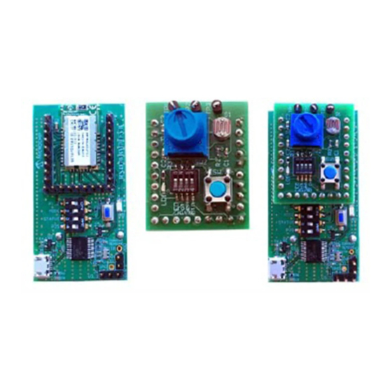
Thank you for purchasing a Microchip Technology BM70/71 PICtail™/PICtail Plus EVB. This chapter provides detailed information about the Microchip Technology BM70/71 EVB. The BM70/71 EVB is designed to evaluate and demonstrate the capabilities of the Microchip BM70/71 Bluetooth Low Energy module. -
Page 200: Bm70/71 Evb Features Overview
• Option to switch power sources between the Coin Cell battery, USB and PICtail interface • UART interface to connect to a host MCU • Connection and test interface between the BM70/71 module and host emulator tools (see Firmware_SoftwareTools_Vx_xx.zip file on Microchip's BM70/71 product pages: www.microchip.com/BM70... - Page 201 BM70/71 PICtail™/PICtail Plus EVB FIGURE 3-1: BM70 EVB (TOP VIEW) The table below provides the details of the components, and the figure below illustrates the top view of the BM70 EVB. TABLE 3-2: BM70 EVB COMPONENTS (BOTTOM VIEW) Block reference...
- Page 202 BM70/71 Bluetooth Low Energy Module User’s Guide ® FIGURE 3-2: BM70 EVB (BOTTOM VIEW) The table below provides the details of the components, and the figure below illustrates the top view of the BM71 EVB. TABLE 3-3: BM71 EVB COMPONENTS (TOP VIEW)
- Page 203 BM70/71 PICtail™/PICtail Plus EVB TABLE 3-3: BM71 EVB COMPONENTS (TOP VIEW) (CONTINUED) Block reference Component reference Description LED2 to LED5, JP5 LEDs and corresponding header test points (for more details, refer to Section 1.1.2.3.1 “General Operation – LED Indication”) GND test point header JP14 PICtail™...
- Page 204 BM70/71 Bluetooth Low Energy Module User’s Guide ® The table below provides details of the components, and the figure below illustrates the top view of the BM70 EVB. TABLE 3-4: BM71 EVB COMPONENTS (BOTTOM VIEW) Block reference Component reference Description —...
-
Page 205: Hardware Features
BM70/71 PICtail™/PICtail Plus EVB HARDWARE FEATURES This section describes the hardware features of the BM70/71 EVB. The BM70/71 EVB provides many options for communicating with other peripheral devices and connecting to various power sources, as illustrated in the figures below. - Page 206 BM70/71 module makes the appropriate connections and provides a USB to UART converter IC on the EVB. This allows the BM70/71 module on the EVB to get power from and communicate with a PC. This makes it easy to use the Microchip provided tools for quick evaluation of the module when a host microcontroller is not available (see Firmware_SoftwareTools_Vx_xx.zip on Microchip product page).
- Page 207 EVB for testing purposes. This allows a user to communicate with and test a BM70/71 module through PC-based tools. The following figure illus- trates how a user can make the blue wire connections to route the communication lines to the external BM70/71 module, bypassing the on-board module of the EVB.
- Page 208 • SW8 – This is a push button switch used to reset the MCP2200 USB to UART converter IC. If a user is seeing errant communication between the PC and the BM70/71 EVB, this push button can be used to reset the internal logic of the USB to UART converter IC.
- Page 209 BM70/71 PICtail™/PICtail Plus EVB 3.3.4 LEDs There are six LEDs on the BM70/71 EVB. These LEDs are used to give the user a visual indication of the BM70/71 module activity/status (for more details, refer to Section 1.1.2.3.1 “General Operation – LED Indication”).
- Page 210 Connected Jumper to pin 5 of the header J3 MCP2200 Tx pin HCI_RXD BM70/71 HCI_RXD (pin 22 of BM70 EVB and pin 7 of BM71 EVB) Connected jumper to pin 7 of the header J3 The table below provides the details of the headers, J10 and J2, which are available for accessing the V and ground/common signal of the BM70/71 EVB.
- Page 211 UART Converter) IC. The signals connected to the GPIO pins of the MCP2200 can be read and driven. On the BM70/71 EVB, they are used to serve as the input for the BM70/71 module output status signals (for a description of signals in Auto Operation, refer to Section 1.1.2.1.2 “Auto Operation –...
- Page 212 BM70/71 Bluetooth Low Energy Module User’s Guide ® The table below provides details of header JP12, used to power an external I C based peripheral on the BM70/71 EVB. TABLE 3-8: I2C INTERFACE (HEADER JP12) Component EVB Signal Header Pin...
- Page 213 MCU to the BM70/71 module on the EVB for testing purposes. The figure below illustrates the con- nection in which the code can be developed and tested for the external MCU before target hardware is fully developed.
-
Page 214: Getting Started - Bm70/71 Evb Example Configuration
® GETTING STARTED – BM70/71 EVB EXAMPLE CONFIGURATION This section provides an understanding of the work flow for evaluating the BM70/71 module. The steps in the sub-sections show a procedure for updating the configuration parameters of the BM70/71 module using the EVB. The procedure demonstrates the connection between the BM70/71 module and smartphone that can be made. - Page 215 Microchip's manufacturing line at the time of releasing this product to market was version 1.06. The latest firmware for each module is made available on the BM70 and BM71 product web pages on Microchip's web- site. For more details, refer to Section 3.5.1 “Programming Proce-...
- Page 216 Section 2.1 “Hardware Interface”). The following list provides some examples of the parameter settings that can be updated on the BM70 module using the UI tool (for the description of features, refer to Section 1.1.1 “Configuration Overview”):...
- Page 217 BM70/71 PICtail™/PICtail Plus EVB 2. In the Loading Option window, click Load Text File to load default configuration parameters (see the figure below). FIGURE 3-10: LOADING OPTION WINDOW 3. From the Open dialog, select the default configuration parameter text file (pro- vided with the Firmware_SoftwareTools_Vx_xx.zip file under the “Con-...
- Page 218 4. From the Configuration Tool window, click Edit to start editing the default parameters (see the figure below). FIGURE 3-12: CONFIGURATION TOOL WINDOW 5. From the Main Feature window, click BLEDK and then click OK (see the figure below). FIGURE 3-13: MAIN FEATURE WINDOW 2016-2022 Microchip Technology Inc. DS50002542C-Page 218...
- Page 219 “BM70_BLE” (or any user-defined name) (see the figure below). Note 1: Click the Help button to get information related to UI parameters. The Auto Operation setting is chosen by default. For more details on BM70/71 behavior under Auto Operation, refer to Section 1.1.2.1 “Auto Operation”. FIGURE 3-14: CONFIGURING PARAMETERS - SYSTEM SETUP ...
- Page 220 7. Click the LE Mode Setup tab and under the Advertising Data Setting section, select Device Name to advertise the device name (see the figure below). This ensures that the name fragment is included in the advertising packet. FIGURE 3-15: ADVERTISING DATA SETTING 2016-2022 Microchip Technology Inc. DS50002542C-Page 220...
- Page 221 .txt log file contains the settings of configuration parameters, which were edited. - Click Write to program these configuration settings into the BM70/71 module. For this to function, the BM70/71 module must be in Configuration mode. 10. To program the configuration parameters on the BM70 module, perform these actions: a) Set switch SW7 in the “ON”...
- Page 222 Ensure that jumpers J1, JP8 and J3 on the BM70 EVB are connected, as illustrated in the figure below. FIGURE 3-18: JUMPER AND BM70 EVB CONNECTION DETAILS c) Connect the USB port (P1) of the BM70 EVB to a PC using the micro-USB cable (see the figure below). FIGURE 3-19: CONFIGURATION SETUP d) On connection, LED1 (blue) and LED6 (red) on the BM70 EVB will turn ON.
- Page 223 BM70/71 PICtail™/PICtail Plus EVB The Read/Write Flash window is displayed. Select the values for COM Port and Baudrate (must be 115200 for the configuration to succeed), and then click Write (see the figure below). FIGURE 3-20: READ/WRITE FLASH g) A message box will appear displaying the message “Write Flash Finish”.
- Page 224 FIGURE 3-22: SW7 IN APPLICATION MODE 3. Connect the BM70 EVB to a PC using the micro-USB cable (see the figure below). LED6 (red) will turn ON solid when USB power is applied to the EVB. LED1 (blue) will turn ON for 50 ms once every three seconds to visually indicate the device is sending connectable advertising packets (standby mode).
- Page 225 BM70/71 PICtail™/PICtail Plus EVB 4. Enable the Bluetooth settings of the phone and then open the mBIoT app (see the figure below). FIGURE 3-24: ENABLING BLUETOOTH AND MBIOT APPLICATION 2016-2022 Microchip Technology Inc. DS50002542C-Page 225...
- Page 226 Low Energy Module User’s Guide ® 5. After the mBIoT app is opened, a user is presented with several choices for communicating with different Microchip Bluetooth modules. Select BM70/BM71 Bluetooth Low Energy UART (see the figure below). FIGURE 3-25: SELECT BM70/BM71 BLUETOOTH LOW ENERGY UART ...
- Page 227 BM70/71 PICtail™/PICtail Plus EVB 6. A list of discoverable devices will be displayed; select the device with the name BM70_BLE to connect with BM70 module (see the figure below). FIGURE 3-26: DISCOVERED DEVICES VIEW 7. Under Connected Device, tap BM70_BLE connected for the device information feature (see the figure below).
- Page 228 BM70/71 Bluetooth Low Energy Module User’s Guide ® 8. Select Device Info to check the device information (see the figure below). FIGURE 3-28: DEVICE INFORMATION 2016-2022 Microchip Technology Inc. DS50002542C-Page 228...
- Page 229 BM70/71 PICtail™/PICtail Plus EVB 9. The device information will be displayed, showing the Bluetooth Low Energy con- nection has been made between the phone app and the BM70 module (see the figure below). FIGURE 3-29: DEVICE INFORMATION 10. The Bluetooth Low Energy link connection is established between the BM70 EVB and an iPhone (see the figure below).
-
Page 230: Firmware Programming Procedure
Figure 3-18. 4. Connect the BM70 EVB to a PC using a micro-USB cable (see the figure below). On connection, LED6 (red) and LED1 (blue) will turn on. Press the Reset button (SW5) to reset the BM70 module. - Page 231 BM70/71 PICtail™/PICtail Plus EVB FIGURE 3-32: FIRMWARE PROGRAMMING SETUP 5. Open the firmware update tool isupdate.exe. Select the COM port and set the following parameters in the tool (see the figure below): - Baud Rate: 115200 - Memory type/subtype: Flash/Embedded Flash - Address: 0x0000 6.
- Page 232 7. If the connection was not successful, the log window will show the string “Con- nect failed”. Verify the parameters input into the tool, press the reset push button on the EVB, and try to “Connect” again (see the figure below). FIGURE 3-34: FIRMWARE UPDATE TOOL WINDOW 2016-2022 Microchip Technology Inc. DS50002542C-Page 232...
- Page 233 BM70/71 PICtail™/PICtail Plus EVB 8. Click Browse to navigate to the folder where the firmware files (.hex) have been downloaded from the Microchip website. In the Open dialog, select all the four hex image files and then click Open (see the figure below).
- Page 234 BM70/71 Bluetooth Low Energy Module User’s Guide ® 9. In the Firmware Update tool window, click Update (see the figure below). FIGURE 3-36: FIRMWARE UPDATE 2016-2022 Microchip Technology Inc. DS50002542C-Page 234...
- Page 235 BM70/71 PICtail™/PICtail Plus EVB 10. The Firmware Update tool will start writing the selected firmware files into the device. Wait until the string “End of Write Memory!” with the elapse time is displayed in the log window (see the figure below).
- Page 236 11. To verify the firmware version, enter the following parameters under the Flash/EEPROM/MCU/AHB Access section, and then click Read (see the figure below): - Address: 0x100E - Length (Hex): 0x02 FIGURE 3-38: ENTERING PARAMETERS 2016-2022 Microchip Technology Inc. DS50002542C-Page 236...
- Page 237 BM70/71 PICtail™/PICtail Plus EVB 12. The Data (Hex) box will display “01 03” and the log window will display the fol- lowing string: “0x01 0x03”. This number represents the firmware version the device was programmed with, in this case version v1.03 (see the figure below).
- Page 238 BM70/71 Bluetooth Low Energy Module User’s Guide ® 2016-2022 Microchip Technology Inc. DS50002542C-Page 238...
-
Page 239: Bm70 Evb Reference Schematics
BM70/71 BLUETOOTH ® LOW ENERGY MODULE USER’S GUIDE Appendix A. BM70 EVB Schematics BM70 EVB REFERENCE SCHEMATICS FIGURE A-1: BM70 EVB SCHEMATICS 2016-2022 Microchip Technology Inc. DS50002542C-Page 239... - Page 240 BM70/71 Bluetooth Low Energy Module User’s Guide ® FIGURE A-2: BM70 EVB SCHEMATICS 2016-2022 Microchip Technology Inc. DS50002542C-Page 240...
-
Page 241: Bm71 Evb Reference Schematics
BM70/71 BLUETOOTH ® LOW ENERGY MODULE USER’S GUIDE Appendix B. BM71 EVB Schematics BM71 EVB REFERENCE SCHEMATICS FIGURE B-1: BM71 EVB SCHEMATICS 2016-2022 Microchip Technology Inc. DS50002542C-Page 241... - Page 242 BM70/71 Bluetooth Low Energy Module User’s Guide ® FIGURE B-2: BM71 EVB SCHEMATICS 2016-2022 Microchip Technology Inc. DS50002542C-Page 242...
-
Page 243: Quick Reference Of Host To Bm70/71 Module Commands
USER’S GUIDE Appendix C. Commands Summary Quick Reference QUICK REFERENCE OF HOST TO BM70/71 MODULE COMMANDS The following table provides all commands the host can send to the BM70/71 module. TABLE C-1: QUICK REFERENCE OF HOST TO BM70/71 MODULE COMMANDS... - Page 244 BM70/71 Bluetooth Low Energy Module User’s Guide ® TABLE C-1: QUICK REFERENCE OF HOST TO BM70/71 MODULE COMMANDS (CONTINUED) Command Type Command Name GATT Client GATT Client - Discover All Primary Services (opcode - 0x30) GATT Client - Discover Specific Primary Ser-...
- Page 245 Commands Summary Quick Reference The following table provides the BM7/71 Module commands available in firmware ver- sion 2.0.1 and above. TABLE C-2: QUICK REFERENCE OF HOST TO BM70/71 MODULE COMMANDS AVAILABLE IN FIRMWARE VERSION 2.0.1 AND ABOVE Command Type Command Name...
-
Page 246: Quick Reference Of Bm70/71 Module To Host Event Responses
Low Energy Module User’s Guide ® QUICK REFERENCE OF BM70/71 MODULE TO HOST EVENT RESPONSES The following table provides all the event responses the BM70/71 module can send to the host. TABLE C-3: QUICK REFERENCE OF BM70/71 MODULE TO HOST EVENT... - Page 247 Tel: 46-31-704-60-40 Tel: 631-435-6000 Sweden - Stockholm San Jose, CA Tel: 46-8-5090-4654 Tel: 408-735-9110 UK - Wokingham Tel: 408-436-4270 Tel: 44-118-921-5800 Canada - Toronto Fax: 44-118-921-5820 Tel: 905-695-1980 Fax: 905-695-2078 2016-2022 Microchip Technology Inc. and its subsidiaries DS50002542C-page 247 09/14/21...
Need help?
Do you have a question about the BM70 and is the answer not in the manual?
Questions and answers