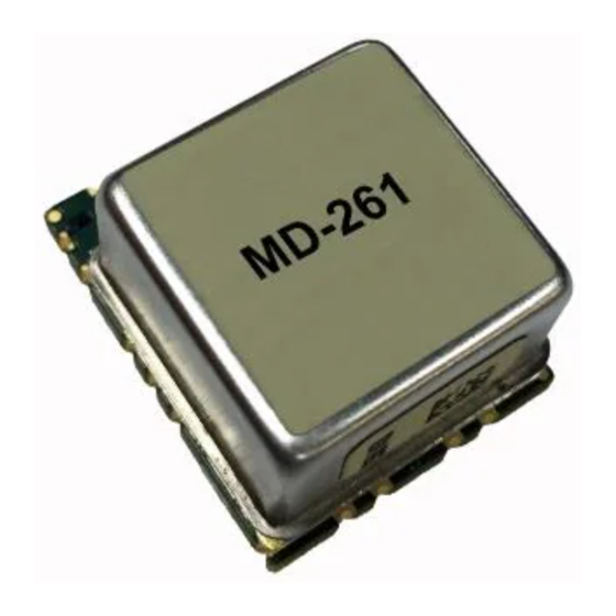
Summary of Contents for Microchip Technology Vectron MD-261
- Page 1 Vectron GNSS Timing Modules MD-261, MD-171, MD-174 Reference Manual Rev D, 10-05-18...
- Page 2 Revision History Revision Date Description 04/02/2015 • First Release 05/21/2015 • Update for Firmware 4.0 12/13/2016 • Update for Firmware 4.3 • Update for Firmware 4.4 • Updated section 2.4.3 Reference 10/05/2018 Selection • Updated section 2.3 Operating Modes Vectron GNSS Timing Module Reference Manual, Rev. D, 10-05-18 Vectron •...
-
Page 3: Table Of Contents
Table of Contents CHAPTER 1 INTRODUCTION ............................- 4 - ..............................- 4 - NTRODUCTION ................................- 4 - COPE ..............................- 4 - ERMINOLOGY CHAPTER 2 DEVICE OPERATION ..........................- 5 - 2.1 S ................................. - 5 - TARTUP .............................. -
Page 4: Chapter 1 Introduction
Chapter 1 Introduction Introduction The Vectron GNSS Disciplined Oscillator Module is an OEM Micro-Disciplined Oscillator Module designed to provide a time and frequency reference to systems requiring synchronization. These modules can be configured to use either GNSS constellations or an external reference signal, which can be 1PPS (standard) or a reference frequency (contact factory). -
Page 5: Chapter 2 Device Operation
Chapter 2 Device Operation Startup At startup or after reset the module may take from five to ten seconds to boot up and begin serial communications. Standard communications startup begins with a $PVEC,03,VECTRON,init_ok… message indicating that the device successfully loaded and initialized all settings. - Page 6 pin. The default interval is once per second, but the intervals for all NMEA messages are configurable. The status information is transmitted using the VEC,00 format. See the VSIP Protocol document for details of the commands and message format. Errors that occur during self-diagnostics or any other stages are reported real-time through error messages and/or the error flag bytes in the status packets.
- Page 7 Opmode 4 – Phase Locking In order to maintain synchronization to the reference source, small frequency corrections to the local oscillator are made. The magnitude of these changes is configurable by the factory depending on application requirements. These corrections happen at variable intervals that are related to the stability of the oscillator and/or reference signal.
-
Page 8: Module Configuration
Module Configuration 2.4.1 Output Messages Configuration The module can be configured at runtime to output various GNSS NMEA talker sentences at user-defined intervals. To configure these messages, use VSIP Command VEC,19 (Configure Messages) at any point during normal device operation. The maximum interval is 255 seconds, while an interval of 0 disables the message. -
Page 9: Reference Selection
2.4.3 Reference Selection The module can lock to either an external reference input or to the internal GNSS receiver’s PPS. If both references are enabled on the module, the device will use whichever is available. If both are enabled and available, the device can be configured to prefer one over the other (GNSS or PPS preferred) or to continuing using the last reference as long as it is available (No Preference). - Page 10 Figure 2.4.3b: Exit from auto holdover process For example, if both GNSS and external PPS references are enabled, and GNSS is preferred, the device will use GNSS whenever it is available. In the event that GNSS reference is lost (i.e. the antenna is disconnected) the device will attempt to switch to the external reference.
-
Page 11: Survey Mode & Position Hold
2.4.4 Survey Mode & Position Hold The module has a Position Hold feature that can be used to provide better timing and positioning solutions if provided with accurate location information. Additionally, a mobile / no survey mode can be enabled as well. By default, the device will use a built-in survey solution that continuously evaluates the devices’... -
Page 12: Gnss System Select
80 degrees elevation. Satellites below the given masks will be reported in GSV messages (satellites with an SNR below the SNR mask will be reported as zero SNR) but not used for position and time calculation. The default elevation mask and signal level mask are 15 degrees and 25 dBHz. 2.4.7 GNSS System Select The module can be configured to use select GNSS Systems for timing and location... -
Page 13: Manual Holdover Mode
2.4.9 Manual Holdover Mode The module can be placed into (or taken out of) manual holdover mode at any time by the user by using VSIP Command VEC,11 (Holdover Mode Set). The device will stay in manual holdover until a power cycle, reset, or another VEC,11 command is sent instructing the device to return to normal operation. -
Page 14: Firmware Updates
Firmware Updates All firmware updates are performed through VDOM Monitor 3. The PC running VDOM 3 should have direct and dedicated serial access to the module’s RX and TX pins for the duration of this process. The reset line should be pulled high or left floating for the entire duration of any firmware update process (unless otherwise specified). -
Page 15: Operation Modes & Condition Registers
Operation Modes & Condition Registers 2.6.1 Operation Modes Opmode Description Evaluating Reference Frequency Locking Phase Alignment Phase Locking Manual Holdover Auto Holdover Test Mode FAULT 2.6.2 Condition Register VEC,00 Condition Register Group Field Description Error Tune Limit OSC EFC approaching limits Antenna Current High GNSS Antenna short / high current Out of Temp Range... -
Page 16: Chapter 3 Device Installation
Chapter 3 Device Installation Serial RX and TX connections While the device will run without any additional control via the serial interface, it is recommended to provide access to the serial RX and TX pins on the customer PCB. A PC running VDOM Monitor 3 with a direct connection (through a USB-to-TTL-Serial converter, for example) to the device is required to perform any firmware updates.


Need help?
Do you have a question about the Vectron MD-261 and is the answer not in the manual?
Questions and answers