
Related Manuals for Microchip Technology BM70 PICtail


Summary of Contents for Microchip Technology BM70 PICtail
- Page 1 ™ BM70 PICtail /PICtail Plus Evaluation Board (EVB) User’s Guide 2015-2016 Microchip Technology Inc. DS70005235C...
- Page 2 WiperLock, Wireless DNA, and ZENA are trademarks of Microchip Technology Incorporated in the U.S.A. and other countries. SQTP is a service mark of Microchip Technology Incorporated in the U.S.A. Microchip received ISO/TS-16949:2009 certification for its worldwide Silicon Storage Technology is a registered trademark of headquarters, design and wafer fabrication facilities in Chandler and Tempe, Arizona;...
- Page 3 BM70 PICTAIL /PICTAIL PLUS EVB USER’S GUIDE Object of Declaration ™ BM70 PICtail /PICtail Plus Evaluation Board 2015-2016 Microchip Technology Inc. DS70005235C-Page 3...
- Page 4 BM70 PICtail /PICtail Plus EVB User’s Guide NOTES: 2015-2016 Microchip Technology Inc. DS70005235C-Page 4...
-
Page 5: Table Of Contents
4.1 Flash Programming Procedure ..............37 Chapter 5. USB-to-UART Converter and Host DUT 5.1 Connecting UART to BM70 EVB DUT ............45 5.2 Connecting UART to Host Microcontroller DUT ........... 46 A.1 Reference Schematics ................. 47 2015-2016 Microchip Technology Inc. DS70005235C-Page 5... - Page 6 BM70 PICtail /PICtail Plus EVB User’s Guide NOTES: 2015-2016 Microchip Technology Inc. DS70005235C-Page 6...
-
Page 7: Document Layout
Document Revision History DOCUMENT LAYOUT ™ This document describes how to use the BM70 PICtail /PICtail Plus EVB (also referred as “BM70 EVB”), as a development tool to emulate and debug firmware on a target board. This user’s guide is composed of the following chapters: •... -
Page 8: Conventions Used In This Guide
This is a caution note. box, or when used in a table or figure, it is located at the Note 1: This is a note used in a bottom of the table or figure. table. 2015-2016 Microchip Technology Inc. DS70005235C-Page 8... - Page 9 Microchip consultant program member listings • Business of Microchip – Product selector and ordering guides, latest Microchip press releases, listings of seminars and events; and listings of Microchip sales offices, distributors and factory representatives 2015-2016 Microchip Technology Inc. DS70005235C-Page 9...
- Page 10 (FAE) for support. Local sales offices are also available to help customers. A listing of sales offices and locations is included in the back of this document. Technical support is available through the web site at: http://support.microchip.com. 2015-2016 Microchip Technology Inc. DS70005235C-Page 10...
- Page 11 Chapter 3. “Getting Started” • Updated Chapter 4. “Flash Programming Procedure” • Updated Chapter 5. “USB-to-UART Converter and Host DUT” • Updated Appendix A. “Schematics” Minor updates to text and formatting were incorporated throughout the document. 2015-2016 Microchip Technology Inc. DS70005235C-Page 11...
- Page 12 BM70 PICtail /PICtail Plus EVB User’s Guide NOTES: 2015-2016 Microchip Technology Inc. DS70005235C-Page 12...
-
Page 13: Chapter 1. Introduction
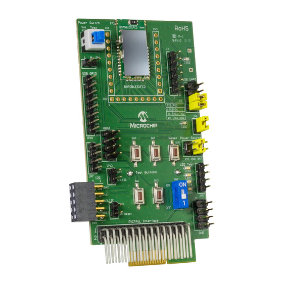
EVB USER’S GUIDE Chapter 1. Introduction ™ Thank you for purchasing a Microchip Technology BM70 PICtail /PICtail Plus Evalua- tion Board (EVB). This document provides detailed information about the BM70 EVB. The BM70 EVB is designed to evaluate and demonstrate the capabilities of the Microchip BM70 BLE module. - Page 14 11. Test button header (J7) 12. I C interface (JP12, JP13) 13. DIP switch (SW7) 14. LEDs and corresponding header pins (JP5) 15. GND header pins (J2) 16. PICtail interface (J8) BM70 EVB (TOP VIEW) FIGURE 1-1: 2015-2016 Microchip Technology Inc. DS70005235C-Page 14...
- Page 15 1. USB-to-UART converter. The switch SW8 is the USB Reset button 2. Module pads 3. Coin Cell battery holder For additional information on these features, refer to Chapter 2. “Hardware”. BM70 EVB (BOTTOM VIEW) FIGURE 1-2: 2015-2016 Microchip Technology Inc. DS70005235C-Page 15...
- Page 16 BM70 PICtail /PICtail Plus EVB User’s Guide NOTES: 2015-2016 Microchip Technology Inc. DS70005235C-Page 16...
-
Page 17: Chapter 2. Hardware
There are three ways to supply power to theBM70 EVB: • Coin Cell battery (socket SK1 for CR2032 battery) • USB • PICtail socket connection 2.1.2 USB connectivity The BM70 EVB provides micro-USB cable connectivity. 2015-2016 Microchip Technology Inc. DS70005235C-Page 17... - Page 18 Power source from Coin Cell Battery, enabled by pin 6 on the jumper bank J1 BM70 power source input TABLE 2-2: GROUND TEST CONNECTOR Part Signal Description Number 1 to 8 Ground test pins 2015-2016 Microchip Technology Inc. DS70005235C-Page 18...
- Page 19 CONNECTOR JP12 Part Description Signal Number JP12 test pin 3V3_I 3V3 voltage of I C interface, short to V for volt- age supply Note: The jumper JP12 must be connected as a default jumper. 2015-2016 Microchip Technology Inc. DS70005235C-Page 19...
- Page 20 Push-Low test buttons, wire connect to test GPIO TABLE 2-12: CONNECTOR JP8 Part Description Signal Number Connected to status LED (LED1) Power source of LED1, short to JP8 pin1 to enable the status LED function 2015-2016 Microchip Technology Inc. DS70005235C-Page 20...
-
Page 21: Chapter 3. Getting Started
• Firmware update tool, isupdate.v4.0.0.207.rar • BLEDK3 Flash code, BT5505_BLEDK3_v103_c1457.rar • BLEDK3 UI tool, IS187x_102_BLEDK3_UI v100.123.rar • mBIoT Utility app, available at App Store for iPhone and at Google Play™ store for Android 2015-2016 Microchip Technology Inc. DS70005235C-Page 21... -
Page 22: Configuring Ui Parameters
Microchip web site: www.microchip.com/bm-70-pictail. In this demonstration, the IS187x_102_BLEDK3_UI_Configuration_Tool v100.123 tool is used. This UI tool version corresponds to the firmware version of the “BLEDK3 v1.03”. FIGURE 3-1: BLEDK3 UI CONFIGURATION TOOL WINDOW 2015-2016 Microchip Technology Inc. DS70005235C-Page 22... - Page 23 FIGURE 3-2: LOADING OPTION WINDOW 4. From the Open dialog, select the default UI parameter text file (provided with the UI tool) and then click Open, see Figure 3-3. FIGURE 3-3: OPEN DIALOG BOX 2015-2016 Microchip Technology Inc. DS70005235C-Page 23...
- Page 24 5. From the UI Configuration Tool window, select UI parameters, and then click Edit, see Figure 3-4. FIGURE 3-4: UI CONFIGURATION TOOL WINDOW 6. From the Main Feature window, click BLEDK and then click OK, see Figure 3-5. FIGURE 3-5: MAIN FEATURE WINDOW 2015-2016 Microchip Technology Inc. DS70005235C-Page 24...
- Page 25 Click the System Setup tab, and in the Name fragment box, type BM70_BLE (or any user-defined name), see Figure 3-6. Note: Click Help button to get the information related to UI parameters. FIGURE 3-6: CONFIGURING UI PARAMETERS - SYSTEM SETUP 2015-2016 Microchip Technology Inc. DS70005235C-Page 25...
- Page 26 /PICtail Plus EVB User’s Guide 8. Click the LE Mode Setup tab, and under the Advertising Data Setting section, select Device Name to advertise the device name, see Figure 3-7. FIGURE 3-7: ADVERTISING DATA SETTING 2015-2016 Microchip Technology Inc. DS70005235C-Page 26...
- Page 27 - Click Write to download UI parameters to Flash 11. To write UI parameters on the BM70 module, perform these actions: a) Set the switch SW7 in the ON position (Test mode), see Figure 3-9. SW7 IN TEST MODE FIGURE 3-9: 2015-2016 Microchip Technology Inc. DS70005235C-Page 27...
- Page 28 On connection, LED1 (blue) and LED6 (red) on the BM70 EVB will turn ON. e) Go to the UI Configuration Tool window, and click Write to download UI parameters on the BM70 module, see Figure 3-8. 2015-2016 Microchip Technology Inc. DS70005235C-Page 28...
- Page 29 Baudrate, and then click Write, see Figure 3-12. FIGURE 3-12: READ/WRITE FLASH g) A message box will appear displaying the message “Write Flash Finish”. Click OK to download UI parameters, see Figure 3-13. FIGURE 3-13: MESSAGE BOX 2015-2016 Microchip Technology Inc. DS70005235C-Page 29...
-
Page 30: Ble Connection To Smartphone
Figure 3-15. Press the Reset button (SW5) to reset the BM70 EVB. On connection, LED6 (red) will turn ON and LED1 (blue) blinks once at an interval. FIGURE 3-15: POWER ON BM70 EVB 2015-2016 Microchip Technology Inc. DS70005235C-Page 30... - Page 31 Getting Started 3. Download the mBIoT app from the App Store and enable the Bluetooth settings on the iPhone, see Figure 3-16. FIGURE 3-16: ENABLING BLUETOOTH AND MBIOT APPLICATION 2015-2016 Microchip Technology Inc. DS70005235C-Page 31...
- Page 32 4. Tap mBIoT app and then tap to open the BM70 BLE UART, see Figure 3-17. FIGURE 3-17: SELECT BM70 BLE UART 5. A list of discoverable devices will be displayed, tap on the BM70_BLE to con- nect, see Figure 3-18. FIGURE 3-18: DISCOVERED DEVICES VIEW 2015-2016 Microchip Technology Inc. DS70005235C-Page 32...
- Page 33 6. Under Connected Device, tap BM70_BLE connected to get the device information, see Figure 3-19 FIGURE 3-19: CONNECTED DEVICE VIEW 7. Tap Device Info to check the device information, see Figure 3-20. FIGURE 3-20: DEVICE INFORMATION 2015-2016 Microchip Technology Inc. DS70005235C-Page 33...
- Page 34 8. The device information will be displayed, see Figure 3-21. FIGURE 3-21: DEVICE INFORMATION 9. The BLE link is established between the BM70 EVB and an iPhone, see Figure 3-22. FIGURE 3-22: BLE LINK CONNECTION 2015-2016 Microchip Technology Inc. DS70005235C-Page 34...
-
Page 35: Bledk3 Auto Pattern And Manual Pattern Tools
BLE UART Transparent, BLE GATT-based transceiver, Bea- con and BeaconThings functionality. For additional information on the BLEDK3 application functionality, refer to the “IS187x_BM7x BLEDK3 Application Note”, which is available at Microchip web site: www.microchip.com/bm-70-pictail. 2015-2016 Microchip Technology Inc. DS70005235C-Page 35... - Page 36 BM70 PICtail /PICtail Plus EVB User’s Guide NOTES: 2015-2016 Microchip Technology Inc. DS70005235C-Page 36...
-
Page 37: Chapter 4. Flash Programming Procedure
3. Connect the BM70 EVB to a PC using the micro-USB cable, see Figure 4-2. On connection, LED6 (red) and LED1 (blue) will turn on. Press the Reset button (SW5) to reset the BM70 module. FLASH PROGRAMMING SETUP FIGURE 4-2: 2015-2016 Microchip Technology Inc. DS70005235C-Page 37... - Page 38 - Baud Rate: 115200 - Memory type/subtype: Flash/Embedded Flash - Address: 0000 On successful connection, “Port connect -> Port Number” message will be displayed, Figure 4-3. FIRMWARE UPDATE TOOL WINDOW - PORT CONNECT FIGURE 4-3: 2015-2016 Microchip Technology Inc. DS70005235C-Page 38...
- Page 39 7. If the connection is failed, “Connect failed” message will be displayed. Verify the parameters and try connecting it again, see Figure 4-4. FIRMWARE UPDATE TOOL WINDOW FIGURE 4-4: 8. Click Browse to display four Flash code files (.hex) downloaded from the Microchip web site. 2015-2016 Microchip Technology Inc. DS70005235C-Page 39...
- Page 40 /PICtail Plus EVB User’s Guide 9. From the Open dialog, select Flash code files and click Open, see Figure 4-5. Note: In this demonstration, the BLEDK3 v1.03 is used. SELECTING FLASH CODE FILES FIGURE 4-5: 2015-2016 Microchip Technology Inc. DS70005235C-Page 40...
- Page 41 Flash Programming Procedure 10. In the Firmware Update tool window, click Update, see Figure 4-6. FIGURE 4-6: FIRMWARE UPDATE 2015-2016 Microchip Technology Inc. DS70005235C-Page 41...
- Page 42 11. The Firmware Update tool will start writing the Flash codes. Wait until the mes- sage “End of Write Memory!” with the elapse time is displayed, see Figure 4-7. FIGURE 4-7: FIRMWARE UPDATE FINISH 2015-2016 Microchip Technology Inc. DS70005235C-Page 42...
- Page 43 12. To verify the firmware version, enter the following parameters under the Flash/EEPROM/MCU/AHB Access section, and then click Read, see Figure 4-8: - Address: “100e” - Length (Hex): “02” FIGURE 4-8: ENTERING PARAMETERS 2015-2016 Microchip Technology Inc. DS70005235C-Page 43...
- Page 44 13. The Data (Hex) box will display the value “01 03” along with the related log infor- mation, see Figure 4-9. FIGURE 4-9: DATA (HEX) VALUE 14. After completing the firmware update, reboot the BM70 EVB using the Reset button (SW5). 2015-2016 Microchip Technology Inc. DS70005235C-Page 44...
-
Page 45: Chapter 5. Usb-To-Uart Converter And Host Dut
UI update. The P2_0 pin is connected to the switch SW7 to switch between Application and Test modes. FIGURE 5-1: UART CONNECTION TO BM70 EVB DUT 2015-2016 Microchip Technology Inc. DS70005235C-Page 45... -
Page 46: Connecting Uart To Host Microcontroller Dut
BM70 EVB through the HCI UART interface by a defined com- mand set. The P2_0 pin is controlled by the MCU to switch between Application and Test modes. FIGURE 5-2: UART CONNECTION TO HOST MICROCONTROLLER DUT 2015-2016 Microchip Technology Inc. DS70005235C-Page 46... -
Page 47: Reference Schematics
BM70 PICTAIL /PICTAIL PLUS EVB USER’S GUIDE Appendix A. Schematics REFERENCE SCHEMATICS FIGURE A-1: BM70 EVB SCHEMATICS 2015-2016 Microchip Technology Inc. DS70005235C-Page 47... - Page 48 BM70 PICtail /PICtail Plus EVB User’s Guide FIGURE A-2: BM70 EVB SCHEMATICS 2015-2016 Microchip Technology Inc. DS70005235C-Page 48...
- Page 49 NOTES: 2015-2016 Microchip Technology Inc. DS70005235C-Page 49...
- Page 50 Tel: 886-2-2508-8600 China - Xian Tel: 631-435-6000 Tel: 86-29-8833-7252 Fax: 886-2-2508-0102 San Jose, CA Fax: 86-29-8833-7256 Thailand - Bangkok Tel: 408-735-9110 Tel: 66-2-694-1351 Canada - Toronto Fax: 66-2-694-1350 Tel: 905-673-0699 Fax: 905-673-6509 07/14/15 2015-2016 Microchip Technology Inc. DS70005235C-Page 50...
Need help?
Do you have a question about the BM70 PICtail and is the answer not in the manual?
Questions and answers