Table of Contents
Advertisement
Quick Links
Advertisement
Table of Contents

Related Manuals for Microchip Technology ExpLoRer


Summary of Contents for Microchip Technology ExpLoRer
- Page 1 ExpLoRer Starter Kit User Guide...
- Page 2 Introducing: ExpLoRer...
- Page 3 Why Arduino?? Open Source Industry standard Easily accessible Free IDEs No flashing tools needed – only a USB cable Simple structure (setup & loop) with examples Excellent HAL Re-use projects across AVR, PIC, Cortex ...
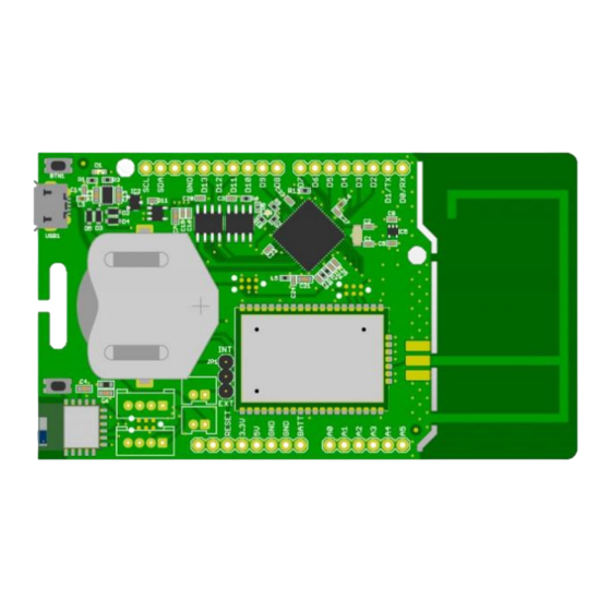
- Page 4 ExpLoRer - Arduino Micro USB: Atmel SAM-D21 Arduino IDE Cortex®-M0+ based & charging microcontroller LiR2450 rechargeable battery 120mAh, 3.6V Standard headers for feature expansion (sensors, GPS, solar)
- Page 5 ExpLoRer - Wireless Low-cost (removable) PCB IFA RN4871 antenna BT-Smart RN2483a Footprint for LoRaWAN optional SMA...
- Page 6 ExpLoRer Blue RGB LED for status Indication MCP9700AT Temperature Sensor Standard headers for feature expansion (sensors, GPS, solar)
- Page 7 ExpLoRer - Security ECC508A Crypto Device...
- Page 8 ExpLoRer Micro USB: Blue ECC508A RGB LED for status Atmel SAM-D21 Arduino IDE Crypto Device Indication Cortex®-M0+ based & charging microcontroller MCP9700AT Temperature LiR2450 Sensor rechargeable battery 120mAh, 3.6V Low-cost (removable) PCB IFA RN4871 antenna BT-Smart RN2xx3 Standard headers Footprint for...
-
Page 9: Specifications
Specifications Microchip ATSAMD21J18 Microcontroller 32-Bit ARM Cortex M0+ Compatibility Arduino M0 Compatible Size 94 x 53 mm Operating Voltage 3.3V I/O Pins Analog Output Pin 12-bit ADC External Interrupts Available on all pins DC Current per I/O pin 7 mA 256 KB (internal) Flash Memory and 4MB (external SST25PF040C flash) - Page 10 Specifications Clock Speed 48 MHz Power 5V USB power and/or 3.7 Lithium battery Solar charge controller, up to 500mA Charging charge current RGB LED, Blue LED LoRa Microchip RN2483a Module Bluetooth Microchip RN4871 Module CryptoAuthentication Microchip ATECC508A Temperature sensor Microchip MCP9700AT Micro USB Port...
- Page 11 Pinout...
-
Page 12: Pins Definition
Pins Definition Definition Pin index Blue LED LED_BUILTIN LED_RED RGB Red LED RGB Green LED LED_GREEN LED_BLUE RGB Blue LED BLUETOOTH_WAKE Bluetooth Wake LORA_RESET LoRa Reset BT_RESET Bluetooth Reset Programmable BUTTON Button TEMP_SENSOR Temperature Sensor Grove Header 14-15 PIN_WIRE_SDA, PIN_WIRE_SCL Grove Header I2C 33-34... - Page 13 Grove connector The Seeedstudio Grove system is a seamless set of open-source plug-and-play components. It simplifies the study and electronic prototypes by proposing a wide selection of sensors and actuators You can find two types of grove connectors on the ...
-
Page 14: Solar Power
Solar power You can plug on the board a solar panel This input has some limitations Maximum voltage : 5.5V Maximum current : 500mA Maximum power : 2.5W You can use a 1.5W Solar Panel for example ... -
Page 15: Arduino Ide
ARDUINO IDE Setup... -
Page 16: Arduino Ide Setup
Arduino IDE Setup Download and install the latest Arduino IDE: https://www.arduino.cc/en/Main/Software... -
Page 17: Board Setup
Board Setup In order to install the board you will need to add the SODAQ board manager URL: http://downloads.sodaq.net/package_sodaq_samd_index.json to File -> Preferences -> Additional Board Manager URLs:... - Page 18 Board Setup Then, the SODAQ SAMD Boards package will appear in the Tools -> Board -> Board Manager Install the latest SODAQ SAMD Boards package Select the SODAQ ExpLoRer board from Tools -> Board ...
-
Page 19: Library Setup
Library Setup Import the libraries provided by using: Sketch -> Include Library -> Add .ZIP Library Then you search for the file named ‘OrangeRn2483.zip’ that you have previously downloaded on https://partner.orange.com/wp-content/uploads/2017/07/OrangeRn2483.zip... - Page 20 Press the reset button twice within a second to place the board into bootloader mode and is expecting a new sketch Select the ExpLoRer COM port assigned Upload the sketch to the board Open the Serial monitor for debugging ...
- Page 21 Arduino IDE and Sketch setup() Loop that runs only once loop() Loop that runs continuously...
- Page 22 Hardware Serials The ExpLoRer has 4 hardware serials: SerialUSB this is for debugging over the USB cable Serial Serial is attached to pin D1/TX and D0/RX Serial1 is connected to the RN4871 Bluetooth module Serial2 is connected to the RN2483 LoRaWAN module ...
- Page 23 Basics sketches The Arduino IDE has some examples built in Open the ExtractHardwareDevEUI sketch File -> Examples -> OrangeRn2483 -> ExtractHardwareDevEUI...
- Page 24 MAIN FEATURES OF THE KIT Getting Started...
-
Page 25: Reset Button
Reset Button On legacy Arduino board the reset button restarts your program from the beginning On the ExpLoRer board the reset button has two modes: Mode 1: simple click that acts as legacy Arduino reset Mode 2: double click that starts the board in a bootloader mode. -
Page 26: Push Button
Push Button The ExpLoRer Starterkit has a programmable button This example will light the built-in Blue LED when the button is pushed void setup() // Configure the button as an input // and enable the internal pull-up resistor pinMode(BUTTON, INPUT_PULLUP) ;... - Page 27 RGB LED int led = LED_RED; // the PWM pin the LED is attached to int brightness = 0; // how bright the LED is int fadeAmount = 5; // how many points to fade the LED by // the setup routine runs once when you press reset: void setup() pinMode(led, OUTPUT) ;...
- Page 28 Temperature Sensor #define debugSerial SerialUSB void setup() pinMode(TEMP_SENSOR, INPUT) ; // Set ADC resolution to 12 bits analogReadResolution(12) ; void loop() // 10mV per C, 0C is 500mV float mVolts = (float)analogRead(TEMP_SENSOR) * 3300.0 / 4096.0 ; float temp = (mVolts - 500.0) / 10.0 ; debugSerial.print(temp) ;...
-
Page 29: Battery Charging
Battery Charging USB power and Solar panel sources can be used for charging Jumpers JP1 determines which battery is used/charged (1) External battery (2) Internal battery ... - Page 30 BLE Module Arduino library for using the Microchip RN487x BLE module #include "RN487x_BLE.h" #define bleSerial Serial1 void setup() rn487xBle.hwInit() ; bleSerial.begin(rn487xBle.getDefaultBaudRate()) ; rn487xBle.initBleStream(&bleSerial) ; if (rn487xBle.swInit()) rn487xBle.enterCommandMode() ; rn487xBle.stopAdvertising() ; rn487xBle.setAdvPower(3) ; rn487xBle.setSerializedName("Microchip") ; rn487xBle.clearAllServices() ; rn487xBle.reboot() ; void loop()
- Page 31 LoRa® Communication Arduino library for using the Microchip RN2483 LoRaWAN module: OrangeRn2483 #include <OrangeRn2483.h> // The following keys are for structure purpose only. You must define YOUR OWN. const int8_t appEUI[8] = { 0x00, 0x00, 0x00, 0x00, 0x00, 0x00, 0x00, 0x00 }; const int8_t appKey[16] = { 0x00, 0x00, 0x00, 0x00, 0x00, 0x00, 0x00, 0x00, 0x00, 0x00, 0x00, 0x00, 0x00, 0x00, 0x00, 0x00 };...
- Page 32 Orange Live Objects Getting Started...
-
Page 33: Let's Get Started
Let’s get started Provision your LoRa end device to join the network devEUI is provided by the ExpLoRer board Get and note the hardware devEUI of the board by using the ExtractHardwareDevEUI sketch The application identifier (appEUI) is 8 bytes long (16 hexadecimal characters). - Page 34 Orange Live Objects Go to the following URL to access Live Objects : https://lpwa.liveobjects.orange-business.com/#/login You can find some useful videos about Live Objects on this website : https://www.youtube.com/channel/UCqiOhIRIpjRvR3Bw0hMLciw...
- Page 35 Provisioning a device Orange Live Objects Create your device within by adding the activation keys and the right profile Choose the profile Michrochip RN2483 DevEui AppEui AppKey...
- Page 36 Provisioning a device In addition to the activation keys you have to choose the profil Microchip RN2483...
- Page 37 Provisioning a device You device is now registered ...
-
Page 38: Testing The Network
Testing the network Open the SendPayload sketch to test your device File -> Examples -> OrangeRn2483 -> SendPayload This sketch will send 3 payloads Modify the file with your own keys in HEX format (0x) // The following keys are for structure purpose only. You must define YOUR OWN. const int8_t appEUI[8] = { 0x00, 0x00, 0x00, 0x00, 0x00, 0x00, 0x00, 0x00 };... - Page 39 Testing the network Upload the sketch to the board Open the Serial monitor for debugging You should see the following monitor : ...
- Page 40 Visualizing Lora Messages To see the 3 payloads that have been sent : On Live Object select your device You are redirected to this page : ...
- Page 41 Visualizing uplinks Click on the uplink tab You can now see the 3 payloads you just sent ...
- Page 42 Downlinks Downlink is about sending payloads from Live Object to the device Click on the downlink tab after selecting your device Then you select the send button Then you fill in the port number and the data to send in ...
- Page 43 Receiving downlinks To visualize your downlink use the GetReceivedData sketch File -> Examples -> OrangeRn2483 -> GetReceivedData Then send the payload from Live Object Finally open the Serial Monitor You should see the data you sent ...
- Page 44 Thank You Note: The Microchip name and logo, dsPIC, MPLAB and PIC are registered trademarks of Microchip Technology Inc. in the U.S.A. and other countries. MiWi, PICDEM and PICtail are trademarks of Microchip Technology Inc. in the U.S.A. and other countries.
Need help?
Do you have a question about the ExpLoRer and is the answer not in the manual?
Questions and answers