Advertisement
*47986707*
47986707
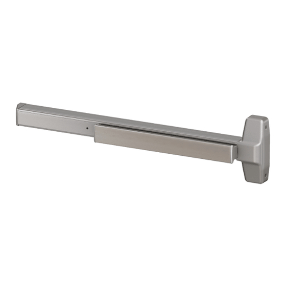
Concealed Vertical Rod Exit Device
Metal Door Applications
QEL7847/47-F (Electric Latch Retraction) Concealed Vertical Rod Exit Device
Devices covered by these instructions:
7847 Concealed Vertical Rod Exit Device
7847-F (Fire) Concealed Vertical Rod Exit Device
CD7847 (Cylinder Dogging) Concealed Vertical Rod Exit Device
Special tools needed:
5/64" hex wrench
#10-24 tap
Drill bits: #25, 1/4", 13/32", 1/2"
Customer Service
1-877-671-7011
7847
Dogging Key
(use with non-fire devices
to lock down pushbar)
• Screw chart ............................. 2
• Door preparation chart ............ 3
• Device installation ................ 4-6
• Adjust rods .............................. 7
• Frame preparation chart .......... 7
• Optional equipment ................
• Cut device .............................. 8
www.allegion.com/us
Installation Instructions
Index:
8
© Allegion 2024
Printed in U.S.A.
47986707 Rev. 04/24-a
Advertisement
Table of Contents

Subscribe to Our Youtube Channel
Related Manuals for Von Duprin 7847


Summary of Contents for Von Duprin 7847
-
Page 1: Table Of Contents
Metal Door Applications Devices covered by these instructions: 7847 Concealed Vertical Rod Exit Device 7847-F (Fire) Concealed Vertical Rod Exit Device CD7847 (Cylinder Dogging) Concealed Vertical Rod Exit Device QEL7847/47-F (Electric Latch Retraction) Concealed Vertical Rod Exit Device Dogging Key... -
Page 2: Screw Chart
SCREW CHART Surface mount or #10-24 x 1” Sex bolts (1-3/4” door) Sex bolts (2-1/4” door) #10-24 x 1-1/2” - Packaged with trim - 785 trims (1-3/4” door) #10-24 x 1-3/8” 785 trims (2-1/4” door) #10-24 x 1-7/8” Surface mount or #10-24 x 3/4”... -
Page 3: Door Preparation Chart
Surface mount **Sex bolts Wood door (cut thru) 1/4” Drill (device side) #25 Drill For all 7847 and #10-24 tap 13/32” Drill (trim side) 7847-F devices: * Prepare holes after lock side of device is mounted and hinge side is equal distance... -
Page 4: Device Installation
Determine Correct Backset, then Mark 4 Holes for Device Center Case Using Template Mark centerline using measuring tape. Place template on centerline mark. Adjust Tailpiece if Needed 7847 7847-F (non-fire rated device) (fire rated device) Make sure tailpiece is installed at correct length for 1-3/4" thick or single or double door 2-1/4"... - Page 5 If Using a Cylinder, Remove Cam and Rotate 180˚ Assemble Rods and Latches and Adjust Length for Proper Door Height Follow red and blue instruction cards on Cam must be in position shown with key removed. If necessary, rods to set initial rod length remove cam screws, place cam is correct position, and reinstall cam screws.
- Page 6 Frame 385-A bottom strike See “Screw Chart” on page 2 for screw STRIKE types and sizes 1" 1/4" undercut for 7847 2 3/4" 2” Minimum clearance (with end cap removed) Threshold application If device is too long for Center 3/8"...
-
Page 7: Adjust Rods
ADJUST RODS Open door and release top Depress pushbar and release. latch bolt as shown (Figure 1). Shown fully Make sure top latch bolt stays Top latch bolt extended retracted as shown. Latch bolt retracted (flush with latch case) Figure 1 Figure 3 Loosen bottom locking screw (Figure 2). -
Page 8: Optional Equipment
OPTIONAL EQUIPMENT - CONTINUED CD (CYLINDER DOGGING) Std. mortise cylinder 1. Remove mortise cylinder cam and reinstall in reverse (Figure 6). 2. Insert key and rotate cam to install the cylinder to the cover plate (Figure 7). 3. Remove key to slide cover plate in position in the mechanism case. Offset toward pushbar Cylinder... - Page 9 This page intentionally blank.
- Page 10 This page intentionally blank.
- Page 11 This page intentionally blank.
- Page 12 This page intentionally blank.
Need help?
Do you have a question about the 7847 and is the answer not in the manual?
Questions and answers