Advertisement
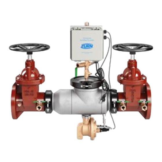
Model 375ASTW1(R) & 375ASTDAW1(R)
Reduced Pressure Principle Assembly (2 1/2", 3", 4" & 6")
Reduced Pressure Detector Assembly (2 1/2", 3", 4" & 6")
*This product contains a weighted average lead content less than 0.25% for wetted surfaces.
Installation Testing Maintenance Instructions
INSTALLATION INSTRUCTIONS
CAUTION: Installation of Backflow Preventers must be performed by qualified, licensed
personnel. The installer should be sure the proper device has been selected for the
particular installation. Faulty installation could result in an improperly functioning device.
ZURN WILKINS Model 375ASTW1 Series Assemblies are for use on potable water lines
where a health hazard exists in the event of a backflow situation.
Damage to the device could result wherever water hammer and/or water thermal expan-
sion could create excessive line pressure. Where this could occur, shock arrestors, check
valves and/or pressure relief valves should be installed downstream of the device.
If installation is in a pit or vault, the Backflow Preventer must never be submerged in
water because this could cause a cross-connection. Make sure that the pit or vault always
remains dry by providing ample drainage. (Consult local codes.)
1. Before installing a Model 375ASTW1 Series Backflow Preventer, flush the line thor-
oughly to remove all debris, chips and other foreign matter. If required, a strainer
should be placed upstream of the Backflow Preventer. CAUTION: Do not use a
strainer in seldom used emergency waterlines such as fire lines.
2. Provide adequate space around the installed unit so that the test cocks will be ac-
cessible for testing and servicing.
3. Install valve at least 12 inches above surrounding flood level.
4. The Model 375 series has been tested and approved in the horizontal position.
Contact factory before installing in other orientations.
5. Always consult local codes for installation methods, approvals and guidance.
MDL 48
250 PSI
DIRECTION OF FLOW
ZURN WILKINS MODEL 375ASTW1
INDOOR HORIZONTAL INSTALLATION
INDOOR INSTALLATION
Indoor installation is preferred in areas that
are subject to freezing conditions. All the
basic installation instructions apply to such
installations. CAUTION: An adequately
sized drain is required to prevent pos-
sible water damage due to relief valve
discharge.
WARNING: Cancer and Reproductive Harm - www.P65Warnings.ca.gov
!
ADVERTENCIA: Cáncer y daño reproductivo - www.P65Warnings.ca.gov
!
AVERTISSEMENT: Cancer et néfastes sur la reproduction - www.P65Warnings.ca.gov
!
Proper performance is dependent upon licensed, qualified personnel performing regular, periodic testing according to ZURN WILKINS' specifications and
prevailing governmental & industry standards and codes and upon following these installation instructions. Failure to do so releases ZURN WILKINS of
any liability that it might otherwise have with respect to that device. Such failure could also result in an improperly functioning device.
PROTECTIVE
ENCLOSURE
C515
12" MIN.
30" MAX.
ZURN WILKINS MODEL 375ASTW1OSY
INDOOR HORIZONTAL INSTALLATION
OUTDOOR INSTALLATION
The Model 375ASTOSYW1 Series
Backflow Preventer may be installed out-
doors only if the device is protected against
freezing conditions. Exposure to freezing
conditions will result in improper function
or damage to the device. The installation
location must be kept above 32°F. All the
basic installation instructions apply.
LEAD-FREE*
12" MIN.
30" MAX.
DIRECTION OF FLOW
(Patent No. 8,997,772)
PLACING THE DEVICE IN SERVICE
1. Start with both shut-off valves closed.
Slowly open the inlet shut-off valve un-
til the backflow preventer is completely
pressurized. A brief discharge from the
relief valve may occur while the device
is pressurizing. The discharge should
cease by the time the shut-off valve is
fully open. If the discharge does not
stop, refer to "MAINTENANCE IN-
STRUCTIONS" for repair procedures.
2. After the device has been pressurized,
vent all trapped air by slightly opening
each of the four test cocks.
3. Slowly open the downstream shut-off
valve. The Model 375ASTW1 Series
Backflow Preventer is now in service.
4. If spitting or intermittent discharges
from the relief valve are noted, it could
be a result of pressure fluctuation
and/or a water hammer condition in
the system. If such conditions exist,
install water pressure reducing valves
or water hammer shock arrestors in
compliance with industry standards as
needed.
5. After the Model 375ASTW1 Series
has been properly installed, test the
device (see "TEST PROCEDURES").
If the device fails the test, remove the
first and second check valves and
thoroughly flush the device. If the relief
valve fails to operate properly, inspect
the sensing passage for clogging (see
"MAINTENANCE INSTRUCTIONS").
Clean rubber seals of all debris and
place unit back in service.
Advertisement
Table of Contents

Related Manuals for ZURN 375ASTW1


Summary of Contents for ZURN 375ASTW1
- Page 1 Proper performance is dependent upon licensed, qualified personnel performing regular, periodic testing according to ZURN WILKINS' specifications and prevailing governmental & industry standards and codes and upon following these installation instructions. Failure to do so releases ZURN WILKINS of any liability that it might otherwise have with respect to that device. Such failure could also result in an improperly functioning device.
-
Page 2: Testing Procedures
Testing Procedures MODEL 375ASTW1 SERIES ASSEMBLY is reported as "closed tight." Go to Test #3. If the differen- Equipment Required: Differential pressure gauge test kit. TEST NO. 1 - RELIEF VALVE OPENING POINT tial pressure reading falls to the relief valve opening point,... -
Page 3: Maintenance Instructions
Replacement 6. Always service the checks one at a time to avoid mixing of worn or damaged parts must only be made with genuine "ZURN parts. Start by removing the hardware and o-rings from the WILKINS"... -
Page 4: Troubleshooting
RK212-375 RK4-350ST 6" 375ASTW1 / 375ASTDAW1 RK212-375R RK212-375 RK6-350ST Performance Characteristics FLOW CHARACTERISTICS MODEL 375ASTW1 2 1/2", 3" & 4" (STANDARD & METRIC) FLOW RATES (l/s) 12.6 25.2 37.9 50.5 3" (80mm) 4" (100mm) 2 1/2" (65mm) FLOW RATES (GPM) MODEL 375ASTW1 6"... -
Page 5: Electronic Emission Notices
Consult an authorized dealer or service representative for help. Zurn is not responsible for any radio or television interference caused by using other than specified or recommended cables and connectors or by unauthorized changes or modifications to this equipment. Unauthorized changes or modifications could void the user's authority to operate the equipment.
Need help?
Do you have a question about the 375ASTW1 and is the answer not in the manual?
Questions and answers