Table of Contents
Advertisement
Quick Links
WHITE-RODGERS
Operator: Save these instructions for future use!
FAILURE TO READ AND FOLLOW ALL INSTRUCTIONS CAREFULLY BEFORE
INSTALLING OR OPERATING THIS CONTROL COULD CAUSE PERSONAL INJURY
AND/OR PROPERTY DAMAGE.
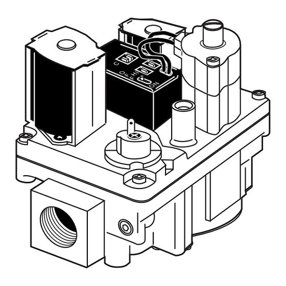
The 36E54-214 combination gas valve is designed for
Direct Spark Ignition and Hot Surface Ignition (HSI) sys-
tem applications. The valve is equipped with redundant
and main solenoid valves that control gas flow to the main
burners, a field-adjustable outlet pressure regulator with
a two-stage solenoid to permit switching between two
preset outlet pressures, and a two-position on/off switch
for electrical shut-off.
Type of Gas: Natural Gas
LP Gas (conversion required)
Pressure Regulator Adjustment Range:
High setting: 3.0 to 12.0" W.C.
Low setting: 1.0 to 8.0" W.C.
PIPE SIZES/CAPACITIES
Pipe Sizes Available
(inches)
1
3
⁄
" x
⁄
" NPT straight through
2
8
1
1
⁄
" x
⁄
" NPT straight through
2
2
CONTENTS
Description ......................................................... 1
Specifications ..................................................... 1
Precautions ........................................................ 2
Installation .......................................................... 2
Adjustment ......................................................... 4
Conversion for L.P. Use ..................................... 5
Lighting Instructions ........................................... 6
ST. LOUIS, MISSOURI 63123-5398
Capacity (BTU/hr) at
1" pressure drop across valve
AGA Std. Nat. Gas
LP Gas
(1,000 BTU/cu. ft.)
(2,500 BTU/cu. ft.)
100,000
162,000
140,000
226,800
Printed in U.S.A.
36E54-214
DSI and HSI Two-Stage
Combination Gas Valve
INSTALLATION INSTRUCTIONS
Ambient Temperature: -40° to 175°F
Pressure Rating: 14" W.C. (
Voltage: 24 VAC, 50/60 Hz
MOUNTING POSITIONS:
Upright, or 0° to 90° from upright
UPRIGHT
LEFT OR RIGHT
INLET
PRESS
TAP
Figure 1. Gas valve mounting positions
DESCRIPTION
SPECIFICATIONS
1
⁄
PSI) max.
2
INLET BOSS
UP OR DOWN
360°
PART NO. 37-6110A
9921
Advertisement
Table of Contents

Subscribe to Our Youtube Channel
Related Manuals for White Rodgers 36E54-214


Summary of Contents for White Rodgers 36E54-214
-
Page 1: Table Of Contents
INSTALLING OR OPERATING THIS CONTROL COULD CAUSE PERSONAL INJURY AND/OR PROPERTY DAMAGE. DESCRIPTION The 36E54-214 combination gas valve is designed for Direct Spark Ignition and Hot Surface Ignition (HSI) sys- tem applications. The valve is equipped with redundant and main solenoid valves that control gas flow to the main... -
Page 2: Precautions
PRECAUTIONS DO NOT BEGIN INSTALLATION UNTIL YOU READ THE FOLLOWING PRECAUTIONS. If you do not follow these instructions exactly, a fire or explosion may WARNING result, causing property damage, personal injury or loss of life. 1. Failure to turn off electric or main gas 4. -
Page 3: Regulator Vent Connection
INSTALLATION (cont’d) NOTE All piping must comply with local codes, ordinances, and/or national fuel gas codes. Drop Drop NOTE: A MANUAL SHUT- Horizontal OFF VALVE MUST BE INSTALLED Horizontal WITHIN 6 FEET OF THE EQUIPMENT Gas Valve Riser NOTE: ALWAYS INCLUDE A DRIP LEG IN Gas Valve Gas Valve... -
Page 4: Adjustment
ADJUSTMENT PRESSURE REGULATOR High Outlet Pressure Adjustment 1. Turn off all electrical power to the system at main fuse ADJUSTMENT or circuit breaker. This valve is shipped from the factory with the regulator 2. Attach a manometer to the outlet pressure tap of the adjusted for use with natural gas. -
Page 5: Conversion For L.p. Use
CONVERSION FOR L.P. USE This gas valve incorporates a pressure regulator capable 4. Locate and remove the slotted head low fire cover of adjustment for both natural gas and propane gas. When screw on the top of the gas valve. The location is converting, it is necessary to approximate the low and marked “LO”... -
Page 6: Lighting Instructions
LIGHTING INSTRUCTIONS FOR YOUR SAFETY READ BEFORE OPERATING If you do not follow these instructions exactly, a fire or explosion WARNING may result causing property damage, personal injury or loss of life. A. This appliance is equipped with an ignition device which •...
Need help?
Do you have a question about the 36E54-214 and is the answer not in the manual?
Questions and answers