Advertisement
Quick Links
TM
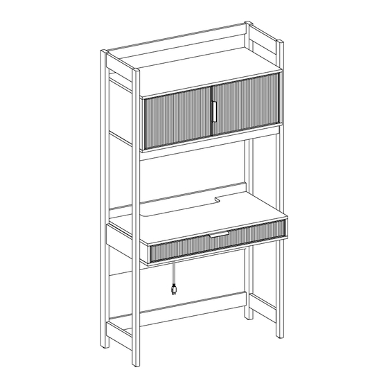
Holmes Desk with hutch
SKU# WEHOL42OS3
For Residential Use Only
Please visit our website for the most current instructions, assembly tips, report damage,or request parts. www.walkeredison.com
Revised 25/03/2024 (D)
©
1
1
Copyright
2024 by Walker Edison Furniture Co., LLC. All rights reserved.
Advertisement

Related Manuals for Walker Edison Holmes WEHOL42OS3


Summary of Contents for Walker Edison Holmes WEHOL42OS3
- Page 1 Holmes Desk with hutch SKU# WEHOL42OS3 For Residential Use Only Please visit our website for the most current instructions, assembly tips, report damage,or request parts. www.walkeredison.com Revised 25/03/2024 (D) © Copyright 2024 by Walker Edison Furniture Co., LLC. All rights reserved.
- Page 2 You can cause cracking or damage to the material and easily strip the hardware. If you choose to use a power tool, your product will no longer be covered under Walker Edison’s warranty. Glue is provided to secure wood dowels in place When inserting dowels, locate the appropriate hole, place a small amount of glue in the hole, and then insert the dowel.
-
Page 3: Parts List
Parts List Part Number Description Quantity Left Panel Right Panel Top Cabinet Panel Bottom Cabinet Panel Left Cabinet Panel Right Cabinet Panel Cabinet Divider Back Cabinet Panel Left Cabinet Door Right Cabinet Door Upper Trim Desk Box Back Panel Support Panel Lower Cabinet Trim Back Drawer Panel Left Drawer Panel... -
Page 4: Hardware List
Hardware List Part Size Name Quantity 8x30mm Wooden dowel 6x35mm Cam bolt 15x11mm Cam lock 6x50mm Bolt 6x30mm Bolt Hex Key M4x57mm Screw 3x12mm Drawer/Cabinet Handle Electrical Outlet Metal Piece 3x12mm Screw Door Hinge... - Page 5 Hardware List Part Size Name Quantity Door Hinge Plastic Pivot Plastic wedge 3x17mm Screw Door Stopper 30mm Sticker Screw 4x25mm Screw 4x15mm Wall Anchor Plastic strap Glue tube 3x15mm Screw...
- Page 6 Hardware List Part Size Name Quantity 4x38mm Screw 15x9mm Cam lock 4x38mm Screw The hardware quantities listed above are required for proper assembly. Extra hardware pieces may be included.
- Page 7 Step 1 Using a screwdriver, attach the Cam Bolts (B) to the Top Cabinet Panel (3).
- Page 8 Step 2 Attach the two Door Stoppers(T) to the Top Cabinet Panel (3) using four 15mm Screws (BB).
- Page 9 Step 3 Insert Wooden Dowels (A) into the dowel holes on the Left Cabinet Panel (5), Right Cabinet panel (6), & the Cabinet Divider (7). The provided glue is to secure wood dowels in place. When first inserting dowels, locate the appropriate hole for the dowel, place a small amount of glue in the hole and insert the dowel.
- Page 10 Step 4 Let’s construct the cabinet. Attach Right Cabinet Panel (6), Cabinet Divider (7), & Left Cabinet Panel (5) to the Top Cabinet Panel (3) using Cam Locks (C). Secure with a screwdriver. Ensure that all panels are facing the correct direction.
- Page 11 Step 5 Slide Back Cabinet Panel (8) into place using the guides.
- Page 12 Step 6 Attach Bottom Cabinet Panel (4) to Left Cabinet Panel (5), Right Cabinet Panel (6), & Cabinet Divider (7) using 50mm Bolts (D).
- Page 13 Step 7 Insert Wooden Dowels (A) into the dowel holes on the Lower Cabinet Trim (15). Then, attach the Lower Cabinet Trim (15) to the Bottom Cabinet Panel (4) using 38mm Screws (CC).
- Page 14 Step 8 Attach the Electrical Outlet ( J) to the Desk Box (12) using 12mm Screws (G). Then, insert Wooden Dowels (A) into the dowel holes on the Desk Box (12).
- Page 15 Step 9 Insert Wooden Dowels (A) into the dowel holes on the Back Panel (13). Using a screwdriver, attach the Cam Bolts (B) into the Back Panel (13).
- Page 16 Step 10 Attach the Back Panel (13) to the Desk Box (12) with two Cam Locks (C) on the bottom side. Then attach two 50mm Screws (EE) through the Back Panel (13) and into the back of the Desk Box (12).
- Page 17 Step 11 Insert Wooden Dowels (A) into the dowel holes on the Upper Trim (11) and the Support Panel (14).
- Page 18 Step 12 Screw Cam Bolts (B) into the Left Panel (1) and the Right Panel (2).
- Page 19 Step 13 Connect the Left Panel (2) to the Upper Trim (11), Lower Cabinet Trim (15), Back panel (13), and Support Panel (14) using Cam Locks (C). Now, connect it to the Right Cabinet Panel (6) using 30mm Bolts (E).
- Page 20 Step 14 Repeat the same steps with the Left Panel (1). Attach Left Panel (1) to the Upper Trim (11), Back Panel (13), and Support panel (14) using Cam Locks (C). Secure with a screwdriver. Then, attach Left Cabinet Panel (5) with two 30mm Bolts (E).
- Page 21 Step 15 Now, secure the front of the Desk Box (12), the Left Cabinet Panel (6), & the Right Cabinet Panel (6) to the Right Panel (2) and the Left Panel (1) using 30mm Bolts (E).
- Page 22 Step 16 Evenly place your Plastic Wedges (R) into the gaps between the Back Cabinet Panel (8) and the frame. Attach the Plastic Wedges with 17mm Screws (S). Insert Plastic Wedge Plastic wedge can be inserted gently between the back panel and frame.
- Page 23 Step 17 Attach the Left Drawer Panel (17) and Right Drawer Panel (18) to the Back Drawer Panel (16) using 38mm Screws (EE).
- Page 24 Step 18 Slide the Bottom Drawer Panel (19) into place using the grooves. Attach the two Drawer Support Panels (20) to the bottom panel and secure with 38mm Screws (EE).
- Page 25 Step 19 Attach Cam Bolts (B) to the Front Drawer Panel (21). Attach the Drawer Pull (H) using 12mm Screws (G).
- Page 26 Step 20 Attach the Front Drawer Panel (21) to the drawer box using Cam Bolts (DD).
- Page 27 Step 21 Cover visible Cam Locks with Stickers (V).
- Page 28 Step 22 Insert drawer into place by lining up the cabinet member and drawer member pieces of your Drawer Glides. Reinserting your Cabinet Glides together Line up the Drawer Member so it is inside the guides of the Cabinet Member. Once the connection is made, push the drawer into place entirely.
- Page 29 Step 23 You’re so close now. Let’s attach the cabinet doors! Attach the Drawer Pulls (H) to the Left Cabinet Door (9) and the Right Cabinet Door (10) using 12mm Screws (G). Next, attach the Metal Pieces (K) to each door using the 12mm Screws (G).
- Page 30 Step 24 Insert Plastic Pivots (Q) into the Bottom Cabinet Panel (4) and Top Cabinet Panel (3).
- Page 31 Step 25 Attach upper Door Hinge (P) by inserting the hinge’s pin into the Plastic Pivot (Q) on Upper Cabinet Panel (3). Next, insert the pin on Door Hinge (N) into the Plastic Pivot (Q) on Lower Cabinet Panel (4). With pin in place, attach Door Hinge (N) to Left Cabinet Door (9) using 12mm Screws (M).
- Page 32 Step 26 Repeating the same process, attach upper Door Hinge (N) by inserting the hinge’s pin into the Plastic Pivot (Q) on Upper Cabinet Panel (3). Next, insert the pin on Door Hinge (P) into the Plastic Pivot (Q) on Lower Cabinet Panel (4). With pin in place, attach Door Hinge (P) to Right Cabinet Door (10) using 12mm Screws (M).
- Page 33 Step 27 Use the adjustable feet to create a level writing surface.
- Page 34 Step 28 Great work, you’re in the home stretch. Let’s secure your bookcase to the wall. Attach the Plastic Strip (Z) to your bookcase using the 12mm Screw (X).
- Page 35 Step 29 Insert the Wall Anchor (Y) into the wall. Next, secure the Plastic Strip (Z) to the wall using the 25mm Screw (W). Warning Serious or fatal injuries can occur from furniture tipping over. To prevent the furniture from tipping over we recommend that it is permanently fixed to the wall.
-
Page 36: Final Assembly
Final Assembly Congratulations on your new piece of furniture! We would love to hear about it and see it. Please leave us a review or post a picture with #mywalkeredisonhome... - Page 37 Assembling furniture can be tricky sometimes. Our customer service team, located in Utah, is here for product information, help assembling a product, or for any other customer support issue Call us at 801-433-3008 Email us at service@walkeredison.com Visit our Customer Service website at walkeredison.com/pages/customer-service We are available to help Monday -Thursday 8am-5pm, Friday 8am-3pm MST...
Need help?
Do you have a question about the Holmes WEHOL42OS3 and is the answer not in the manual?
Questions and answers