Advertisement
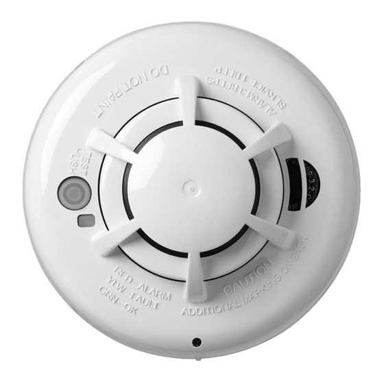
SMD-429 PG2 Wireless Heat Detector
Installation and Operating Instructions
Read this instruction sheet thoroughly before installation and use of the SMD-429 PG2 HEAT
Introduction
The SMD-429 PG2 HEAT is a wireless heat detector with a fixed temperature and rate of rise
heat sensor and an internal piezoelectric alarm.
The following versions are available:
Frequency (MHz)
Version
915
SMD-429 PG2
Compatible Devices
This detector is compatible with UL/ULC Listed Visonic Control Panels and Qolsys IQ Panel
2+. For UL/ULC installations use this device only in conjunction with compatible IQ2 wireless
receivers and PowerG receivers. Transmissions occur at approximately 915 MHz (912 MHz to
919 MHz).
Operation
During normal operation, the green LED flashes every 60 seconds.
The detector goes into alarm when the heat level exceeds 135 ºF / 58 ºC and automatically
restores when the heat level falls below the threshold. The detector also goes into alarm
when the temperature rapidly increases over a short period of time. During an alarm, the
LED flashes once per second and the sounder emits the evacuation temporal pattern.
Region
Middle East
Detector Trouble
If the detector has a general fault, the yellow LED blinks once every four seconds and
emits a chirp every 48 seconds. After four hours, the panel displays a fire trouble message.
Detector and Status
Status
LEDs
Normal
Double Green flash every 60 seconds
Heat Alarm Red flash every 1 second
Heat Test
Red flash every 1 second
Test Alarm
(button
Red flash every 1 second
press)
Detector
Yellow flash every 4 seconds
Trouble
Low Battery Yellow flash every 12 seconds
Power-up
Red, yellow, green, flash sequence
Red, yellow, green flash sequence every
Tamper
12 seconds
Wireless Transmissions
A supervisory message is transmitted at 64 minute intervals. If the signal is not received, the
control panel determines that the detector is missing.
The detector transmits the following:
Alarm / Alarm Restore -Transmitted at time of occurrence.
NOTE: During an alarm condition, the detector sends an alarm event to the
control panel. When the condition is restored, the detector sends an alarm
restore event to the panel and sets the alarm restore indicator. The red LED
blinks once every four seconds until the Alarm in memory is cleared. You can
clear the alarm restore indicator from the control panel or press and hold the
test button for five seconds.
Tamper / Tamper Restore - (tamper switch activated) ten- second
Indication
Sounder
Off
ANSI S3.41 temporal 3
ANSI S3.41 temporal 3
ANSI S3.41 temporal 3
One chirp every 48 seconds
One chirp every 48 seconds
(press button to hush for 12 hours)
One chirp at the end of the power-up
sequence
Off
Advertisement
Table of Contents

Related Manuals for Johnson Controls tyco Visonic SMD-429 PG2


Summary of Contents for Johnson Controls tyco Visonic SMD-429 PG2
- Page 1 Detector Trouble If the detector has a general fault, the yellow LED blinks once every four seconds and emits a chirp every 48 seconds. After four hours, the panel displays a fire trouble message. Detector and Status Indication SMD-429 PG2 Wireless Heat Detector Sounder Status LEDs...
-
Page 2: Battery Installation And Replacement
maximum delay on restore before transmission. Low Battery - (battery voltage falls below threshold). Battery voltage is tested & transmitted at the time of a supervisory or other transmissions. Trouble - (detector fault limit reached). Troubles are transmitted at the time of occurrence (one trouble per supervisory interval). - Page 3 Power up the device (insert battery) to start the PowerG association process. 5. Test Unit NOTE: The central monitoring station, if used, should be notified prior to the test being generated. This prevents a false alarm and an unnecessary response from the central monitoring station.
-
Page 4: Diagnostic Test
(Installer are planning renovations or repainting, take precautions to avo id dust, paint or Diagnostic mode) or the User code (User Diagnostic mode) to test. chemical contamination to the detector. CAUTION: The diagnostic test cannot be performed when the tamper is open. Testing and maintenance procedures shall be in accordance with CAN/ULC -S552-14. -
Page 5: End User License Agreement
* damage arising out of any other abuse, mishandling or improper application of the Products. The user must follow the Manufacturer’s installation and operational instru ctions including testing the Product and its Items Not Covered by Warranty: In addition to the items which void the Warranty, the following items shall not be whole system at least once a week and to take all necessary precautions for his/her safety and the protection of his/her covered by Warranty: (i) freight cost to the repair centre;... - Page 6 Limitations on Reverse Engineering and Derivative Works. You may not reverse engineer, decompile, or disassemble the Soft ware, and and applicable export control measures administered by the U.S. Department of Commerce and U.S. Department of State, any attempt to do so shall immediately terminate this EULA - except and only to the extent that such activity may be expressly any other U.S.
-
Page 7: Regulatory Information
(Visonic Ltd.) could void the user’s authority to operate the equipment. © 2020 Johnson Controls. All rights reserved. JOHNSON CONTROLS, TYCO and VISONIC are trademarks and/or registered trademarks. Unauthorized use is strictly prohibited. D-308313 SMD-429 PG2 Wireless Heat Detector Rev. 0 (12/20) EMAIL: info@visonic.com...
Need help?
Do you have a question about the tyco Visonic SMD-429 PG2 and is the answer not in the manual?
Questions and answers