
Subscribe to Our Youtube Channel
Related Manuals for Autarco LH-MII Series


Summary of Contents for Autarco LH-MII Series
- Page 1 Hybrid Solar Inverters Hybrid Solar Inverters LH-MII-series Installation and Operation Manual IM-S2.LH-MII-EN-V1.4 IM-S2.LH-MII-EN-V1.4...
- Page 2 Keep this manual for future info@autarco.com reference. www.autarco.com Product information is subject to change without notice. All trademarks are Address recognized as the property of their respective owners. Torenallee 20 5617 BC Eindhoven © Autarco Group B.V. The Netherlands All rights reserved. IM-S2.LH-MII-EN-V1.4 IM-S2.LH-MII-EN-V1.4...
- Page 3 Tables of contents Hybrid Solar Inverters Introduction Read this first Target Audience Product versions covered by this document Preparation Safety instructions Package contents Internal DC switch Explanations of symbols on inverter Product information Overview Product identification Product overview Intelligent LED indicators Password Reset Mounting Safety...
- Page 4 Tables of contents Hybrid Solar Inverters Smart Meter installation Communication cable assembly 5.6.1 Protective cover for communication ports 5.6.2 Communication Port Definition 5.6.3 BMS Port connection 5.6.4 Meter Port connection 5.6.5 DRM Port Connection (Optional) 5.6.6 RS485 Port Connection (Optional) 5.6.7 Parallel Terminal Connection (Optional) Parallel System Wiring...
-
Page 5: Read This First
This manual contains important information for use during installation and maintenance of the LH-MII series Autarco inverters. To reduce the risk of electrical shock, and to ensure the safe installation and operation of Autarco inverters, the following safety symbols appear throughout this document to indicate dangerous conditions and important safety instructions. -
Page 6: Product Versions Covered By This Document
Product versions covered Hybrid Solar Inverters by this document The main purpose of this user manual is to provide instructions and detailed procedures for installing, operating, maintaining, and troubleshooting the LH-MII series of Autarco inverters which includes the following models: • S2.LH5000-MII •... -
Page 7: Safety Instructions
Please contact your dealer to get the information of authorized repair facilities for any maintenance or repairmen. Any unauthorized actions including modification of product functionality of any form will affect the validation of warranty service; Autarco may deny the obligation of warranty service accordingly. IM-S2.LH-MII-EN-V1.4... -
Page 8: Packing List
1x Dust Cover 6x RJ45 connector 1x Bluetooth Antenna 1x User Manual Manual Internal DC switch Your Autarco LH-MII series inverter is equipped with an internal DC switch. This switch can be found on the left side of the inverter. IM-S2.LH-MII-EN-V1.4... -
Page 9: Explanations Of Symbols On Inverter
Explanations of symbols Hybrid Solar Inverters on inverter DANGER - HIGH ELECTRIC VOLTAGE 10 min This device is directly connected to the public grid. All work to the inverter shall be carried out by qualified personnel only. There might be residual currents in inverter for up to 10 minutes because of large capacitors. -
Page 10: Product Information
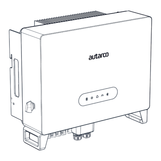
Hybrid Solar Inverters Overview Autarco LH-MII series hybrid inverters are state of the art, high efficiency, robust and reliable inverters. They are easy to install and carry a standard 5-year product warranty, extendable up to 15 years. Our rigorous quality control and testing facilities guarantee Autarco inverters meet the highest quality standards possible. - Page 11 Hybrid Solar Inverters 3.2 Front view DC Switch 3.3 Bottom view Battery Input Data Logging Stick AC Backup Port DC Switch PV Input Communication Antenna AC Grid Port IM-S2.LH-MII-EN-V1.4...
-
Page 12: Password Reset
Intelligent LED indicators Hybrid Solar Inverters There are five indicators on the Autarco LH-MII Series Hybrid Inverter (Battery, Power, WiFi, RS485 and Bluetooth) which indicate the working status of the inverter. The Bluetooth Antenna or WiFi datalogger shall be installed on the Antenna/COM port of the hybrid inverter before local debugging. - Page 13 Mounting Hybrid Solar Inverters Safety DANGER! Do not install the inverter near flammable or explosive items. WARNING! The installation must be performed by qualified personnel and in compliance with national and local standards and regulations. This inverter will be connected to a high voltage DC power generator and AC grid. Inappropriate installation may also jeopardize the life span of the inverter.
-
Page 14: Mounting Instructions
Mounting instructions Hybrid Solar Inverters ATTENTION! Two people are required to remove the inverter from the carton and install the inverter. Handles are formed into the heatsink for ease of handling the inverter. • The inverter is suitable for outdoor and indoor installation. •... -
Page 15: Safety Clearance
Safety clearance Hybrid Solar Inverters CAUTION! Make sure heat sinks are out of reach of children. WARNING! When installing multiple inverters, make sure there is sufficient clearance between them. High temperatures may affect performance. Make sure inverter controls are reachable in case of emergency. -
Page 16: Installation
WARNING! No matter what kind of grounding connection is adopted, it is strictly forbidden to connect the ground of the inverter with the lightning protection of a building, otherwise Autarco will not be responsible for any damage caused by lightning. - Page 17 Hybrid Solar Inverters IMPORTANT! After crimping the terminal to the wire, inspect the connection to ensure the terminal is solidly crimped to the wire. Step 5 Remove the screw from the heat sink ground point. Step 6 Use the screw of the ground point to attach the grounding cable (as shown as in Figure 5.3). Tighten the screw securely.
-
Page 18: Battery Connection
Hybrid Solar Inverters DANGER! Do not connect the strings with an open circuit voltage greater than the Max DC voltage of the inverter. DANGER! For protection against electric shock, MC4 connectors must be isolated from the PV array while being assembled or disassembled. DC connections must not be unplugged while under load. - Page 19 Hybrid Solar Inverters Step 2 Connect the battery ends to the battery module positive and negative terminals. If connecting Dyness Tower batteries, please follow steps 3 to 6, otherwise skip to step 6. Step 3 Insert the stripped wire with twisted litz wires all the way in. The wire ends must be visible in the spring.
- Page 20 Hybrid Solar Inverters AC Grid & Backup port connection 5.4.1 AC Grid Port is to connect to the grid and AC Backup Port is to connect to the critical load circuit. AC-BACKUP Terminal AC-GRID Terminal AC-BACKUP AC-GRID ANTENNA NOTE! AC Backup Connector is longer while the AC Grid Connector is shorter Table 5.1 AC Grid &...
- Page 21 Hybrid Solar Inverters 3. Crimp wires, screw torque 0.8Nm ± 0.1Nm 5.11 AC Grid & Backup connectors AC Grid AC Backup 4. Push Housing into Body until you hear a “click” sound. 5.12 Housing CLICK 5. Insert seal body (B), and claw into it, then tighten the Nut with torque 2.5Nm ± 0.5Nm. 5.13 6.
- Page 22 Hybrid Solar Inverters WARNING! It is important that the AC wires are connected to the right terminals as indicated by the “L1”, ‘’L2’’, ‘’L3’’, “N” and “Ground” symbols on each AC connector. Damage to the inverter by wrong connections are not covered under warranty! In some countries a second protective conductor is required.
-
Page 23: Smart Meter Installation
Smart Meter installation Hybrid Solar Inverters Autarco’s LH-MII series hybrid inverter must be connected with the supplied Eastron meters to fulfill the control logic of the self-consumption mode, export power control, monitoring, etc. An Eastron 3ph meter (With CT): SDM630MCT is provided as default in the inverter box. - Page 24 Communication cable assembly Hybrid Solar Inverters The Autarco LH-MII series inverter uses RS485 cable to communicate with the Meter and the CAN-bus to communicate with the battery’s Battery Management System (BMS). NOTE! The CAN cable enables the communication between the inverter and the Li-ion battery, please check for latest model compatibility before installation.
- Page 25 Hybrid Solar Inverters 5.6.2 Communication Port Definition 5.19 Communication ports Reserved DO/DI RS485 Meter AC-BACKUP AC-GRID ANTENNA Table 5.2 Inverter communication ports Port Function Used for CAN communication between inverter and Lithium battery BMS. Meter Used for RS485 communication between inverter and the smart meter. It is necessary to realize the normal hybrid control logics.
- Page 26 Hybrid Solar Inverters 5.6.3 BMS Port connection Take out the pre-made CAN cable from the package and connect one end to battery CAN port and then connect another end to the inverter BMS port. Cable Length: 3 meters. 5.20 Pre-made BMS cable in Inverter package (cable Length: 3 meters) NOTE! Pin definition of the BMS Port is as follows: EIA/TIA 568B.
- Page 27 Pin 3: Reserved; Pin 4: Reserved Pin 5: Switch_input1; Pin 6: Switch_input2 Switch_input1 Switch_input2 Pin 7: Reserved; Pin 8: Reserved DRM (logic interface) NOTE! To use this function, please contact Autarco if this function is supported in your country. IM-S2.LH-MII-EN-V1.4...
- Page 28 If a 3rd party external device or controller needs to communicate with the inverter, the RS485 port can be used. Modbus RTU protocol is supported by Autarco inverters. To acquire latest protocol document, please contact Autarco local service or Autarco sales team.
- Page 29 Parallel System Wiring Hybrid Solar Inverters 5.25 Parallel system wiring Inverter 1 (Master) Battery Inverter 2 (Slave) Battery Inverter 3 (Slave) Battery Grid Backup Load IM-S2.LH-MII-EN-V1.4...
- Page 30 S2.LH10000-MII 400 V The Autarco inverter is equipped with an integrated Residual Current Protective Device (RCPD) and Residual Current Operated Monitor (RCOM). The RCOM will detect leakage currents and compare it with the expected value; if the leakage current exceeds the permitted range, the RCPD will disconnect the inverter from the AC load.
- Page 31 For connection instructions, please refer to the respective Autarco Monitoring Device installation manuals. The USB type COM port at the bottom of the inverter can connect to Autarco’s USB data loggers to realize the remote monitoring via MyAutarco. Please see below, list of compatible Autarco data loggers compatible with this device: •...
-
Page 32: Commissioning & Configuration
Commissioning & Configuration Hybrid Solar Inverters Preparation & Commissioning ATTENTION! Autarco’s installer app is mandatory for installing your LH-MII inverter! Before switching on the inverter, please make sure that: • You have downloaded and installed Autarco’s Installer App. • The device is accessible for safe operation, maintenance, and service. -
Page 33: Monitoring Setup
Visit www.autarco.com to download the latest version of our app. • You can search “Autarco” in Google Play or Apple App Store to find the latest version of our app. • You may scan the QR code below to download the Installer App. - Page 34 Autarco app will display the inverter model selected in Helios during project design. Step 5 Select the monitoring stick connected to the inverter and scan its QR code to retrieve the serial number. Monitoring can be setup via 4G / WIFI / LAN. Please follow Autarco’s monitoring stick manuals for further instructions.
- Page 35 Hybrid Solar Inverters ATTENTION! To continue inverter configuration, you must - • Ensure a compatible Autarco monitoring stick is connected to the inverter’s COM port. • Ensure a reliable WIFI / LAN / 4G network is present. Step 6 Once the monitoring device is connected, you may click “Next” and “Save setup”.
-
Page 36: Inverter Configuration
Inverter Configuration Hybrid Solar Inverters You can view inverter details in the app. Press “Set up inverter” to configure it for the first time. Step 1 Configure the Date and Time for your inverter. You may at any point retrieve the inverter’s current settings. - Page 37 Hybrid Solar Inverters Step 3 Select the right “Meter type” & “Meter function” for your installation. Selection must be based on the meter type you are actually connecting to the inverter. If there is no meter connected at this moment, please select “No meter” to avoid alarms. We suggest to select “Meter in grid”...
- Page 38 Hybrid Solar Inverters Step 5a Turn on and use “Grid trading schedule” if manual control of battery charging and discharging is required with respect to time. Set the charge and discharge current (A) for your battery. You may set up to 3 time slots in the grid trading schedule by pressing “Add time slot”. Step 5b “Allow charge from grid”...
-
Page 39: Operating Modes
Operating modes Hybrid Solar Inverters As seen in Section 6.3, the inverter can operate in various operational logics, suiting individual needs. ATTENTION! Symbols depict “Power consumption” priority. 6.5.1 Self-use mode This mode stores excess PV power into the battery. If the battery is charged, or there is no battery, the excess PV power will be exported back to the grid/utility company. - Page 40 Hybrid Solar Inverters 6.2 Grid trading mode priority 6.5.3 Off-grid mode Off-grid mode must only be used by systems that are not electrically connected to the grid at all. This mode is almost like Self-Use Mode, but the PV power will be curtailed if the battery is sufficiently charged, and the domestic load demand is lower than the amount of available PV power.
-
Page 41: Temperature Derating
Hybrid Solar Inverters 6.5.5 Grid Trading Schedule (Time of Use) Grid Trading Schedule is used to customize when and by how much the battery may be allowed to charge or discharge. If the grid trading schedule is turned on, the inverter will only follow this schedule to determine when to charge or discharge the battery. -
Page 42: Maintenance
CAUTION! Never use any solvents, abrasives, or corrosive materials to clean the inverter. The LH-MII series inverters require general maintenance to be performed once per year. Impurities such as dust and dirt accumulation on the heat sink may negatively affect the inverter’s ability to dissipate heat. -
Page 43: Troubleshooting
Troubleshooting Hybrid Solar Inverters Message Name Information Description Troubleshooting Suggestion Control device to shutdown Turn on the device in the ON/OFF Setting. LmtByEPM The device's output is under - Confirm whether the inverter is connected to an external EPM/meter to prevent controlled reverse current. - Page 44 Hybrid Solar Inverters Message Name Information Description Troubleshooting Suggestion Over-Load Load overload fault Backup load power is too large, or some inductive load startup power is too large, need to remove some backup load, or remove the inductive load on the backup. BatName-FAIL Wrong battery brand selection Confirm whether the battery model selection is consistent with the actual one.
- Page 45 NOTE! If the inverter displays any alarm message as listed above: please turn off the inverter and wait 5 minutes before restarting it. If the fault persists, contact your installer or Autarco. Before contacting us, please have the following information available: •...
-
Page 46: Product Specifications
Product specifications Hybrid Solar Inverters Technical Data S2.LH5000-MII S2.LH6000-MII Input DC (PV side) Recommended max. PV power 8000W 9600W Max. input voltage 1000V Rated voltage 600V Start-up voltage 160V MPPT voltage range 200-850V Full load MPPT voltage range 200-850V Max. input current 16A/16A/16A Max. - Page 47 Hybrid Solar Inverters Technical Data S2.LH8000-MII S2.LH10000-MII Input DC (PV side) Recommended max. PV power 12800W 16000W Max. input voltage 1000V Rated voltage 600V Start-up voltage 160V MPPT voltage range 200-850V Full load MPPT voltage range 200-850V 250-850V Max. input current 16A/16A/16A/16A Max.
- Page 48 Hybrid Solar Inverters Technical Data S2.LH8000-MII S2.LH10000-MII Protection Anti-islanding protection AFCI Insulation Resistor detection Residual current monitoring unit Output over current protection Output short protection Output over voltage protection DC switch DC reverse polarity protection PV overvoltage protection Battery reverse protection General data Dimensions(W/H/D) 600*500*230mm...
- Page 49 S2.LH10000-MII Battery connection Quick Connection plug AC connection Quick Connection plug Display LED + Bluetooth + APP Communication CAN, RS485, Optional:Wi-Fi, Cellular, LAN Warranty 5 years (extend to 20 years) Scan the QR Code to download Autarco’s Installer app! IM-S2.LH-MII-EN-V1.4...
Need help?
Do you have a question about the LH-MII Series and is the answer not in the manual?
Questions and answers