
Related Manuals for Autarco PELD10-MII


Summary of Contents for Autarco PELD10-MII
- Page 1 Installation and Operation Manual Power Export Limitation Device PELD10-MII IM-S2.1P&3P-PELD10-MII-EN-V1.0 Manual...
- Page 2 This manual is an integral part of the unit. Please read the manual carefully before installation, operation or maintenance. Keep this manual for future reference. Product information is subject to change without notice. All trademarks are recognized as the property of their respective owners. © Autarco Group B.V. All rights reserved.
-
Page 3: Table Of Contents
1 Introduction 1.1 Read this first 1.2 Target Audience 1.3 Intended Application 2 Preparation 2.1 Safety instructions 3 Overview 3.1 Front Panel Display 3.2 LED Status Indicator Lights 3.3 Keypad 3.4 LCD 4 Installation 4.1 Install location 4.2 Mounting the EPM 4.3 Electrical Connections 4.4 Make the Grid input cable 4.5 Make RS485 cable (COMM-INV port) - Page 4 6.4.2 Backflow Power 6.4.3 Set CT Parameter 6.4.4 Failsafe ON/OFF 6.4.5 Failsafe settings 6.4.6 Backflow Work Mode 6.4.7 PELD ON/OFF 6.4.8 System Upgrade 6.4.9 Set Password 6.4.10 Restore Settings 6.4.11 Set EPM Regulator 7 Set Inverters 8 Troubleshooting 8.1 Checklist 8.2 Other Troubleshooting 9 Specifications 9.1 Single phase PELD specifications...
-
Page 5: Introduction
1.2 Target Audience This manual is intended for anyone who uses Autarco inverters in conjunction with a Power Export Limiting Device (PELD). Before any further action, the operators must first read all safety regulations and be aware of the potential danger to operate high-voltage devices. Operators must also have a complete understanding of this device’s features and functions. -
Page 6: Intended Application
1.3 Intended Application This manual applies to the following products: ● S2.1P-PELD10-MII For limiting up to 10 single phase inverters at a time ● S2.3P-PELD10-MII For limiting up to 10 three phase inverters at a time Please note that all current inverter models, excluding the UX Series, are capable of internal power export limitation using an external current clamp or consumption meter. -
Page 7: Preparation
Please contact your dealer to get the information of an authorized repair facility for any maintenance or repairmen. Any unauthorized actions including modification of product functionality of any form will affect the validation of warranty service; Autarco may deny the obligation of warranty service accordingly. -
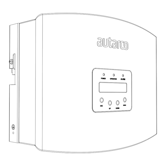
Page 8: Overview
3 Overview 3.1 Front Panel Display Figure 3.1: Front display 3.2 LED Status Indicator Lights There are three LED status indicator lights at the front panel of the inverter, as shown in figure 3.1. Light Status Description Export Device power on POWER Export Device power off Communication with inverter... -
Page 9: Installation
4 Installation 4.1 Install location To select a location for the PELD, the following criteria should be considered: ● The temperature of the PELD can reach up to 75℃. ● The PELD is designed to work in extended temperature range from -25℃ to 60℃. ●... - Page 10 Hang the PELD in the bracket by the steps below (see figure 4.3) Figure 4.3: Hang the PELD in the bracket Fix the two screws at the side of the bracket to secure the PELD. Do not overtighten the screws. See figure 4.4.
-
Page 11: Electrical Connections
PELD is listed below: Grid AC voltage sampling terminal CT1/2/3 AC current sampling terminals (for 1 phase, only use CT1) Comm_INV Communication with Autarco inverter Communication Connection for Monitoring Device or Software Upgrade Stick Figure 4.5: Three-phase system with Autarco S2.3P-PELD-MII... - Page 12 Figure 4.6: Three phase system with Autarco S2.3P-PELD-MII Figure 4.7: Single phase system with Autarco S2.1P-PELD-MII Note that the PELD shall be installed near the measuring point for current/voltage. The CT cables and grid input cable are usually limited in length. In order to shorten the length of the CT and grid input cable, the PELD is recommended to be installed near the customer distribution box.
-
Page 13: Make The Grid Input Cable
Measure the distance from the PELD to the mains distribution box. Choose the proper cable for grid input. Use a 5-core cable for Autarco 3 phase PELD and a 3-core cable for Autarco single phase PELD. Carefully check the connections in the connector and make sure the cables inside the connector cannot touch each other. -
Page 14: Make Rs485 Cable (Comm-Inv Port)
4.5 Make RS485 cable (COMM-INV port) ● Refer to figure 4.16, the RS485 terminals for inverter and PELD are already assembled. RS485A is connected to yellow and RS485B to blue wire. Suggested RS485 cable: preferred 0.5-1.0mm ● Refer to figure 4.17, connect the communication cable between the inverter and the PELD, then measure the distance from PELD to inverter. -
Page 15: Connect The Ground Cable
● Follow step1 to assemble 2 connectors to each end of the cable. If the RJ45 comms ports are used on the inverter, you also may use standard Ethernet cables for connection from one inverter to the second one and so on. Then you only need to assemble one cable from the last inverter to PELD. ●... -
Page 16: Connect The Grid Input To The Distribution Box
In figure 4.20 a few examples of Current Transformers can be found. It is possible to select your own brand and type as long as they meet the requirements and safety standards. Autarco has a limited number of 300 : 5 Current Transformers in stock and they must be ordered separately. Check space requirements in your installation. -
Page 17: Multiple Inverter Connection
Before starting up the inverter, please follow 6.5.1 to set the inverter number in the PELD. 4.10 Monitoring Inverters that are connected to the PELD can be monitored by Autarco Ethernet/WiFi/GPRS stick or box. WiFi/GPRS/Ethernet stick is used for single inverter monitoring. In case of a single inverter, always check if using the internal PELD function with an external meter is an alternative. -
Page 18: Commission And Decommission
5 Commission and decommission 5.1 Commissioning ● Connect the CT connectors, grid input terminal, RS485 terminal (INV) and monitoring device (if needed) to the PELD. Connect the other end of RS485 cable to the inverter(s). Figure 5.1 Cable connections ● Close the breaker of the grid input and start up PELD ●... -
Page 19: Operation
6 Operation 6.1 Introduction During normal operation, the display alternately shows the power of the grid side and the operation ‘’Status’’. Screens can also be scrolled manually by pressing the UP and DOWN keys. Press the ENTER key to access to the Main Menu. There are 4 status messages: ●... -
Page 20: Information
6.2.1 Information Autarco PELD main menu provides access to operational data and information. The information is displayed by selecting ‘’Information’’ from the menu and then scrolling up or down through the list. See figure 6.1. Figure 6.1: Information list 6.2.2 Lock Screen Pressing the ESC key returns to the Main Menu. -
Page 21: Settings
6.2.3 Settings The following submenus are displayed when the Settings menu is selected. ● Set Time ● Set Address 6.2.4 Set Time This function allows time and date setting. When this function is selected, the LCD will display a screen as shown in Figure 6.3 Figure 6.3: Set time Press the UP/DOWN keys to set time and data. -
Page 22: Inverter Power
Note: it is possible that NG will be shown when the current-transformer is connected correctly if the cable is smaller than designed for. Make sure the cable lies centralized in the core for proper reading. For the single phase S2.1P-PELD10-MII only one CT is shown. 6.3.3 Software The screen shows the model version and the software version of the PELD. -
Page 23: Communication Data
Figure 6.9: Model inverter 6.3.5 Communication data The screen shows the internal communication data of the inverter. This page is for service technicians only. Figure 6.10: Communication data 6.4 Advanced Settings-Technicians Only Notice: Access to this area is for fully qualified and accredited technicians only. Please follow 6.4 to enter password to access this menu The default password is “0010". -
Page 24: Set Ct Parameter
Figure 6.12: Set backflow power Press the UP/DOWN keys to set data. Press the ENTER key to set backflow power, then press UP/DOWN keys to change the number (in units of 100 Watt). Press the ESC key to save the settings and return to the previous menu. 6.4.3 Set CT Parameter This function is used to change CT parameters if the customer selects a different CT. -
Page 25: Failsafe Settings
6.4.5 Failsafe settings Failsafe settings determine how the inverter operates if there is a loss of connection with any device. There are 3 error modes ● RS485 AllFail: PELD has lost communication with ALL inverters ● RS485 Fail: PELD has lost communication with one or more inverters ●... -
Page 26: Peld On/Off
Figure 6.16: Mode 01 Mode “02” is the per phase limiting mode. In this mode the export power is 0 on each phase. The inverter will generate a power equal to the lowest load power. See the example in figure 6.17: the inverter only generates power equal to the lowest power of the three phases (here 4000 W). -
Page 27: System Upgrade
Switching PELD on: the device can monitor and manage the working condition of inverters in real time, and it prevents backflow generated. Switching PELD off means the device shuts down the function of controlling backflow power. 6.4.8 System Upgrade The upgrade of PELD’s system can be realized through the RS485 communication port with an upgrade stick. -
Page 28: Set Inverters
The PELD is available with different operation modes. To make sure that the inverters can work with the MII version, set the inverters into the correct operation mode. Notice: If you are using S2.PELD10-MII, select 5G EPM Notice: If 5G EPM is chosen, all inverters produced before Nov 30th 2019 need to update the firmware. -
Page 29: Troubleshooting
8 Troubleshooting The PELD is designed in accordance with the most important international safety and EMC requirements. Before delivering to the customer, the PELD has been subjected to several tests to ensure its optimal operation and reliability. 8.1 Checklist Please check the following; ●... -
Page 30: Specifications
9 Specifications 9.1 General specifications... -
Page 31: Single Phase Peld Specifications
9.2 Single phase PELD specifications 9.3 Three-phase PELD specifications...
Need help?
Do you have a question about the PELD10-MII and is the answer not in the manual?
Questions and answers