
Related Manuals for Fritsch premium line PULVERISETTE 14


Summary of Contents for Fritsch premium line PULVERISETTE 14
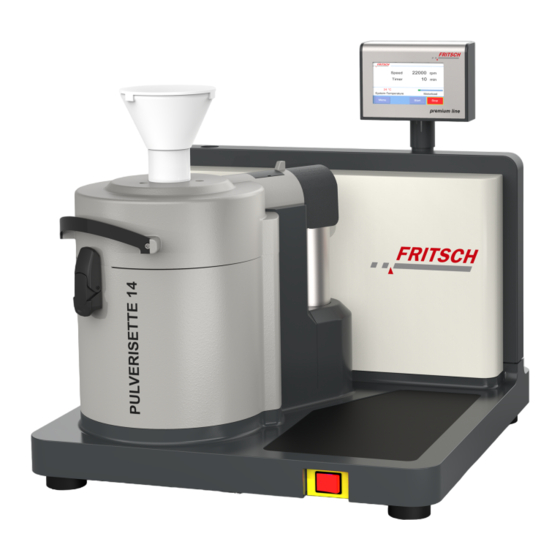
- Page 1 Operating instructions VARIABLE SPEED ROTOR MILL premium line PULVERISETTE 14 Valid starting with: 14.6020/00001 Read the instructions prior to performing any task! Translation of the original operating instructions...
- Page 2 Fritsch GmbH Milling and Sizing Industriestrasse 8 D - 55743 Idar-Oberstein Telephone: +49 6784 70-0 Email: info@fritsch.de Internet: www.fritsch.de Version 06/2022 Index 008...
- Page 3 Certifications and CE conformity Certification Fritsch GmbH has been certified by the SGS-TÜV Saar GmbH. An audit certified that Fritsch GmbH conforms to the requirements of the DIN EN ISO 9001:2015. CE Conformity The enclosed Conformity Declaration lists the guidelines the FRITSCH instrument...
-
Page 4: Table Of Contents
Table of contents Table of contents Basic structure..........Safety information and use. - Page 5 Table of contents Initial start-up..........Switching on.
-
Page 6: Basic Structure
Basic structure Basic structure Display Collecting vessel lid Lock pin Collecting vessel Rotor Rotor holder Sieve insert 10 Hood Labyrinth disk 11 Funnel Main switch... -
Page 7: Safety Information And Use
This operating manual is not a complete technical description. Only the details required for operation and maintaining usability are described. Fritsch has prepared and reviewed this operating manual with the greatest care. However, no guarantee is made for its completeness or accuracy. -
Page 8: Operating Principle
Safety information and use NOTICE The PULVERISETTE 14 premium line has been built according to the state of the art and in accordance with recognized safety rules. During operation, however, hazards can arise for users or third parties and damage to the machine or other material property can occur. -
Page 9: Speed Control
Neither compliance with this manual nor the conditions and methods used during installation, operation, use and maintenance of the PULVERISETTE 14 premium line can be monitored by Fritsch GmbH. Improper execution of the installation can result in property damage and thus endanger persons. Therefore,... - Page 10 Safety information and use WARNING This symbol and keyword combination points out a possibly hazardous situation that can result in death or serious injury if not avoided. CAUTION This symbol and keyword combination points out a possibly hazardous situation that can result in slight or minor injury if not avoided.
- Page 11 Safety information and use WARNING This symbol and keyword combination points out a directly hazardous situation due to hot surfaces. Ignoring information with this designation can result in serious burn injuries due to skin contact with hot surfaces. Safety information in the procedure instructions Safety information can refer to specific, individual procedure instructions.
-
Page 12: Device Safety Information
Immediately replace damaged or illegible information signs. ■ Unauthorised alteration of the PULVERISETTE 14 premium line will void Fritsch's declaration of conformity to European directives and void the guar- antee. ■ Only use the PULVERISETTE 14 premium line when it is in proper working order, as intended and in a safety- and hazard-conscious manner adhering to the operating manual. -
Page 13: Protective Equipment
Safety information and use Protective equipment Protective equipment is to be used as intended and may not be disabled or removed. All protective equipment is to be regularly checked for integ- rity and proper functioning. For start-up, the housing cover (10) has to be closed. The housing cover is locked during operation. -
Page 14: Hazardous Points
Safety information and use Hazardous points WARNING − Crushing hazard when closing the housing cover! − Crushing hazard when removing and positioning the col- lecting vessel! − The collecting vessel can become very hot! − Never operate the device without a sieve ring. −... -
Page 15: Technical Data
Technical data Technical data Dimensions 520 x 630 x 550 mm (width x height x depth) Weight Weight: 44 kg (net) Operating noise Operation condition of device during measurement: 0.2 mm sieve ring, 12-rib steel rotor with max. speed (22000 rpm), source material: Rice. ■... -
Page 16: Final Fineness
Technical data 3.10 Final fineness The achievable final fineness depends largely on the sample properties and the grinding element used. -
Page 17: Installation
Compare the contents of your delivery with your order. Please store the transport packaging so that it can be reused if you need to return the product. Fritsch GmbH accepts no liability for damage caused by improper packaging (packaging that is not from Fritsch). -
Page 18: Ambient Conditions
Installation Strong temperature fluctuations can occur during transport or interim storage. Depending on the temperature difference between the installation site and the transport or storage environment, condensation can form inside the device. This can damage the electronics if the devices are switched on too early. Wait for at least two hours after setup before switching on the device. -
Page 19: Prepare Power Cord
Installation Prepare power cord DANGER Changes to the connection line may only be made by a quali- fied person. The Variable speed rotor mill requires a mains power supply with 200 - 240 V at a mains frequency of 50 - 60 Hz for proper operation. Prepare the power cable as follows: Fig. - Page 20 Installation Fig. 2: 3 phases, 4 wires earthed 230 / 400 V...
- Page 21 Installation Fig. 3: 3 phases, 4 wires earthed 130 / 230 V If you have a question, please contact our technical service. E-Mail: schmell@fritsch.de or telephone: +49 6784 70279.
-
Page 22: Electrical Connection
‘Exhauster Cyclone’ connection can also be manually switched on separately in the menu for exhausting after a comminution. NOTICE Fritsch mills are speed controlled. The devices are equipped for this with frequency converters. In order to comply with the EMC directive, many measures must be taken to prevent operational transient emissions. -
Page 23: Initial Start-Up
Initial start-up Initial start-up Perform initial start-up only after all work as described in ⮫ Chapter 4 ‘Installa- tion’ on page 17 has been carried out. Switching on ■ Connect the device to the mains. ■ Switch on the device with the main switch (7) on the front of the device. ■... -
Page 24: Using The Device
Using the device Using the device WARNING If the grinding elements used are not original accessories, we assume no guarantee and exclude all liability for damage to the device or for personal injury. WARNING Make certain before starting the machine that the grinding elements have been properly installed and locked in place and that there are not any loose parts inside of the device. -
Page 25: Impact Element
Using the device NOTICE Risk of melting! Feed material with unknown properties or material with a low melting point to the device in small quantities. After test grinding, check the grinding elements for melting. If this is the case, the comminution material must be "embrittled" before grinding with the PULVERISETTE 14. -
Page 26: Sieve Ring
Grinding tools are not covered by the warranty terms of FRITSCH GmbH! Sieve rings with trapezoidal perforation, available as orig- inal accessories from Fritsch, can have manufacturing sieve opening tolerances of up to +/- 20% of the nominal mesh width. - Page 27 Using the device Carefully set the labyrinth disk (7) over the motor mounting flange (8) until it lies flush on the motor mounting flange (8). For this, pay attention to the temperature sensor – it must fit into the bore hole on the underside of the labyrinth disk.
-
Page 28: Cutting Insert
Using the device Cutting insert 6.2.1 Cutting rotor The cutting rotor with cooling fins is equipped with 3 rotor blades. These are available as hardened, stainless steel (14.6590.00) and as tungsten carbide (14.6595.00). For use in heavy metal and iron-free grinding, the cutting rotor is available with rotor blades and fixed knifes also made of titanium (14.4690.00) and zirconium oxide (14.6595.00). -
Page 29: Inserting The Cutting Insert
Using the device The fixed knives can be removed using a Torx 20 key. When unscrewing the fixed knives, be aware that they are under spring pressure and can shoot out when loos- ening the screws. When reinstalling the knives, always observe the direc- tion of rotation of the rotor. - Page 30 Using the device We recommend the use of a high-performance cyclone in combination with an extraction system. This provides a better and quicker throughput and cools the system. To use the PULVERISETTE 14 premium line as a cutting mill, the accessories must be installed as follows: Position the special labyrinth disk in the grinding chamber.
- Page 31 Using the device Then place the lid on the collecting vessel and close the grinding chamber via the touch screen. Continue with ⮫ Chapter 6.3 ‘Conducting a grinding operation’ on page 33 . 6.2.3.1 Setting the gap width of the knives Also watch the corresponding video on YouTube: ⮫ ...
- Page 32 Using the device Turn the screws on the individual fixed knives clockwise using a Torx 20 key – the knives are moved outwards against the springs and the gap increases. When turning anticlockwise, the springs will push the knives inwards and the gap decreases.
-
Page 33: Conducting A Grinding Operation
Using the device Conducting a grinding operation CAUTION Wear hearing protection! Hearing protection should be worn when grinding, because noise levels can reach or exceed 75.9 dB(A). Chapter 5.2 After closing the PULVERISETTE 14 premium line as described in ⮫ ‘Function check’... -
Page 34: Grinding With External Cooling
Using the device Lift off the lid of the collecting vessel (1) and, moving outwards with a brush, clean the grinding stock from the outer surface of the sieve ring (4) and from the inner edge of the collecting vessel (6). If source material falls downward, it does not directly enter the device;... -
Page 35: External Cooling
Using the device 6.5.1 External cooling It is possible to exchange the lower ventilation grate on the rear panel against a cover plate (order no. 14.4214.00) with a connector for a vacuum cleaner (order no. 43.9070.00). This will provide faster airflow, thus cooling the system! Grinding with heavy-metal-free or metal-free grinding elements To eliminate the influence of even the smallest amounts of iron, it is necessary to install iron-free grinding elements. -
Page 36: Continuous Feeding Of Source Material
Using the device Continuous feeding of source material The volume of continually fed source material may not exceed the volume of the inserted collecting vessel. To feed larger quantities of a free-flowing source material, use the vibratory feeder "LABORETTE 24". ■... -
Page 37: Grinding With The Impact Bar Insert
Using the device Grinding with the impact bar insert For the item numbers, please refer to our homepage or the spare parts cata- logue. Collecting vessel lid O-ring 98 x 2 Lid seal Sieve ring Impact bar Rotor Collecting vessel Labyrinth disk with O-rings To carry out grinding with a process similar to that of a cross beater mill, there is an optional insert with impact bar (5) and an outer sieve ring (4). -
Page 38: Factors With An Impact On Grinding
Using the device Factors with an impact on grinding Source material feed rate The smaller the feed rate of source material, the larger the share of fine particles and the circulation of air. The mechanical and temperature load on the mill decrease. -
Page 39: Control Panel
Using the device 6.10 Control panel When the mill is switched on, the values of the last grinding are displayed. Other [Menu] button in order to change parameters can be selected by clicking on the the following settings: ■ Parameter: Speed settings from 6000 - 22000 (rpm), selectable in steps of 1000. -
Page 40: Accessories
Accessories Accessories High-performance cyclone separator Dust exhaust connection Mill connection 2 x bushing for spiral hose (45.5984.16) 1x hose sample exhaustion (45.5979.16) 1x sample bottle 1000 ml (83.3250.00) Collecting vessel for sample exhaustion with cyclone separator (optional accessory) The high-performance cyclone separator is suited for sample materials that are sensitive to temperatures. - Page 41 Accessories NOTICE During the grinding process, use the Cyclone exhaust system to ensure that the air flows freely through the funnel: − Choose a sample quantity that will not clog the funnel. − Do not use an inner funnel. (classic line) −...
-
Page 42: Small Volume Cyclone Separator
In case a sterilisation is necessary, Fritsch recommends soaking the filters in 100 % isopropanol for an hour and then air-drying for at least 12 hours. - Page 43 Accessories Particle inlet pipe for connecting to the collecting vessel Outlet pipe, collecting vessel premium line PULVERISETTE 14 The small volume Cyclone separator can be used for the sample exhaustion of small sample quantities! Connect all parts as shown in the previous image. Switch on the exhaust system.
-
Page 44: Cleaning
Cleaning Cleaning DANGER Mains voltage! − Before beginning with cleaning work, disconnect the mains plug and protect the device against being unintentionally switched back on! − Do not allow any liquids to flow into the device. − Indicate cleaning work with warning signs. −... -
Page 45: Maintenance
Maintenance Maintenance DANGER Mains voltage − Before beginning with maintenance work, unplug the mains plug and protect the device against being uninten- tionally switched back on again! − Indicate maintenance work with warning signs. − Maintenance work may only be performed by specialised personnel. -
Page 46: 10 Repairs
Repairs 10 Repairs DANGER Mains voltage! − Before beginning with repair work, unplug the mains plug and protect the device against being unintentionally switched back on. − Indicate repair work with warning signs. − Repair work may only be performed by specialised per- sonnel. -
Page 47: 11 Disposal
FRITSCH is not obliged to take back used FRITSCH devices. FRITSCH declares it is prepared to take back used FRITSCH devices for recycling or disposal free of charge whenever a new device is purchased. The used FRITSCH device must be delivered free of charge to a FRITSCH establishment. -
Page 48: 12 Guarantee Terms
Rectification may take the form of either repair or replacement of the device, at our sole discretion. The guarantee may be redeemed in all countries in which this FRITSCH device is sold with our authorisation. - Page 49 NOTICE Please note that in the event that the device must be returned, the device must be shipped in the original Fritsch packaging. Fritsch GmbH denies all liability for any damage due to improper packaging (packaging not from Fritsch).
-
Page 50: 13 Exclusion Of Liability
The supplied products as well as this operating manual conform to the current state of the art when they leave the sphere of influence of FRITSCH GMBH. - Page 51 Neither compliance with this operating manual nor the conditions and methods used during installation, operation, use and maintenance of the product can be monitored by Fritsch GmbH. Improper execution of the installation can result in property damage and thus endanger persons. Therefore, we assume absolutely...
-
Page 52: 14 Safety Logbook
Safety logbook 14 Safety logbook Date Maintenance / Repair Name Signature... -
Page 53: 15 Index
Index 15 Index Accident prevention........7 Maintenance. - Page 54 Index...
- Page 56 © 2019 Fritsch GmbH Milling and Sizing Industriestrasse 8 D - 55743 Idar-Oberstein Telephone: +49 6784 70-0 Email: info@fritsch.de Internet: www.fritsch.de...
Need help?
Do you have a question about the premium line PULVERISETTE 14 and is the answer not in the manual?
Questions and answers