
Related Manuals for Fritsch PULVERISETTE 13 premium line


Summary of Contents for Fritsch PULVERISETTE 13 premium line
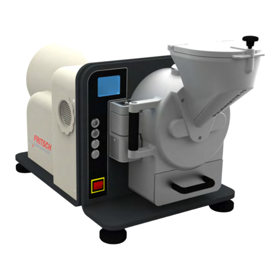
- Page 1 Operating instructions DISK MILL PULVERISETTE 13 premium line Valid as of: 13.30XX/30000 Read the instructions prior to performing any task! Translation of the original operating instructions...
- Page 2 Fritsch GmbH Milling and Sizing Industriestraße 8 55743 Idar-Oberstein Telephone: +49 (0)6784/ 70-0 Fax: +49 (0)6784/70-11 Email: info@fritsch.de Internet: www.fritsch.de Version 10/2014 Index 001...
- Page 3 Certifications and CE conformity Certification Fritsch GmbH has been certified by the TÜV-Zertifizierungsgemeinschaft e.V. An audit certified that Fritsch GmbH conforms to the requirements of the DIN EN ISO 9001:2008. CE Conformity The enclosed Conformity Declaration lists the guidelines the FRITSCH instrument conforms to, to be able to bear the CE mark.
-
Page 4: Table Of Contents
Table of contents Table of contents Basic structure................6 Safety information and use............7 2.1 Requirements for the user............. 7 2.2 Scope of application............... 7 2.2.1 Operating principle............. 8 2.3 Obligations of the operator............ 8 2.4 Information on hazards and symbols used in this manual..9 2.5 Device safety information............ - Page 5 Table of contents 6.8 Grinding with grinding disks of zirconium oxide....30 6.9 Adding material..............31 6.10 Taking samples..............32 6.11 Final fineness..............33 Accessories................... 34 7.1 Dust extraction..............34 7.2 Dosed sample feeding with the LABORETTE 24 vibratory feeder................... 36 7.3 Comminution of coarse material in combination with the Jaw Crusher PULVERISETTE 1 premium line......
-
Page 6: Basic Structure
Basic structure Basic structure Display 14 Housing cover Control panel 15 Airfilter Mains switch + key (changing the parameters and the gap width, Funnel menu navigation) Fixed grinding disk - key (changing the parameters and the gap width, Movable grinding disk menu navigation) Gap setting screw Up arrow key (menu navigation) -
Page 7: Safety Information And Use
Subject to technical modifications. 2.2 Scope of application The PULVERISETTE 13 premium line is a disk mill for fine grinding by batches or continuously fine grinding of hard-brittle to medium-hard solids from the field of mining and metallurgy, geology and mineralogy, and the glass and ceramics industry. -
Page 8: Operating Principle
2.3 Obligations of the operator Before using the the PULVERISETTE 13 premium line, this manual is to be carefully read and understood. The use of the the PULVERISETTE 13 pre- mium line requires technical knowledge; only commercial use is per- mitted. -
Page 9: Information On Hazards And Symbols Used In This Manual
Neither compliance with this manual nor the conditions and methods used during installation, operation, use and maintenance of the the PUL- VERISETTE 13 premium line can be monitored by Fritsch GmbH. Improper execution of the installation can result in property damage and thus endanger persons. - Page 10 Safety information and use DANGER! This symbol and keyword combination points out a directly hazardous situation due to electrical current. Ignoring information with this designation will result in serious or fatal injury. DANGER! This symbol and keyword combination designates con- tents and instructions for proper use of the machine in explosive areas or with explosive substances.
-
Page 11: Device Safety Information
Safety information and use Example: Loosen screw. CAUTION! Risk of entrapment at the lid. Close the lid carefully. Tighten screw. Tips and recommendations This symbol emphasises useful tips and recommenda‐ tions as wells as information for efficient operation without malfunction. Further designations To emphasise procedure instructions, results, lists, references and other elements, the following designations are used in this manual:... - Page 12 Fritsch's declaration of conformity to European directives and void the guarantee. Only use the the PULVERISETTE 13 premium line when it is in proper working order, as intended and in a safety- and hazard-conscious manner adhering to the operating manual. In particular, immediately rectify any malfunctions that could pose a safety hazard.
-
Page 13: Protective Equipment
Safety information and use 2.6 Protective equipment Protective equipment is to be used as intended and may not be disabled or removed. All protective equipment is to be regularly checked for integrity and proper functioning. The disk mill features many safety devices: The funnel (4) is protected against being reached into by a grid. -
Page 14: Hazardous Points
Safety information and use The locking switch (13) pulls in the grinding stock container after grinding starts and locks it with the lock pin that is attached to the container (9). The locking switch monitors whether the device has been properly closed during operation. It also prevents a start-up when the disk mill is open. -
Page 15: Protection Against Restart
Safety information and use 2.8.2 Protection against restart The device shuts down if there is a power outage. The mill comes to a standstill within seconds. Grinding stock container can only be opened by an emergency release (k) on the inside of the device. For that, the housing cover (14) needs to be removed as follows. -
Page 16: Technical Data
Technical data Technical data 3.1 Dimensions 52 x 105 x 63 cm (width x depth x height) 3.2 Weight 228 kg without grinding disks (net) 246 kg with grinding disks made of tungsten carbide 3.3 Operating noise Emissions value of workplace according to DIN EN ISO 3746:2005 L 68.9 dB(A). -
Page 17: Final Fineness
Technical data 3.7 Final fineness The final fineness lies between 0.05 and 12 mm. - 17 -... -
Page 18: Installation
Installation Installation 4.1 Transport The device is delivered on a transport pallet with a wooden cover. We recommend using a forklift or pallet truck for transporting the packed device. DANGER! Do not step under the transport pallet during transport. WARNING! Improper lifting can lead to personal injury or property damage. - Page 19 Installation To set up the disk mill, you need a crane or a different suitable transport device as well as 2 harnesses (not included in the scope of delivery) that are at least 40 cm long and have a capacity of 500 kg. CAUTION! The weight of the disk mill is approx.
-
Page 20: Ambient Conditions
Installation Lash the harness to a crane or another hoist. Next lash the harness to the two eyelets provided for this. Using the crane, bring the disk mill to the desired position. Make sure the device does not swing while it is being transported. Remove the harness. -
Page 21: Adapting To The Mains
Installation 4.5.1 Adapting to the mains The PULVERISETTE 13 premium line is delivered with a connection voltage adapted to the electrical system of your country. - 21 -... -
Page 22: Initial Start-Up
Initial start-up Initial start-up The disk mill is delivered with a mounted grinding disk. Check the gap width before the first grinding. (See Ä Chapter 6.4 „Setting the gap width“ on page 27). After the disk mill has been set up as described in Ä... -
Page 23: Using The Device
Using the device Using the device WARNING! If the grinding elements used are not original accesso- ries, we provide no guarantee and exclude all liability for damage to the device. WARNING! Make sure before starting the machine that the grinding disks have been mounted properly and that there are not any loose parts inside the device. -
Page 24: Control Panel
Using the device 6.1 Control panel When the grinding chamber is open, the button (h) for locking the grinding chamber is not lit. The button (h) flashes green as the grinding chamber closes by motor, and continues flashing until it is closed. Then it stays lit green. During the start-up, the Start button (e) flashes green. -
Page 25: Setting The Zero Point
Using the device Menu change To switch from the "Parameter" menu to the "Check/Setup" menu, press the arrow keys (c,d) until the - and + symbols on the bottom right of the display have a black background. Switch to the Check/ Setup menu then by pressing the keys + (a) or - (b). - Page 26 Using the device To switch from the "Parameter" menu to the "Check/Setup" menu, press the arrow keys (c,d) until the - and + symbols on the bottom right of the display have a black background. Switch to the Check/ Setup menu then by pressing the keys + (a) or - (b). Close and lock the grinding chamber and take out the grinding stock container.
-
Page 27: Setting The Gap Width
Using the device Once the smallest gap width has been set and a minimal friction of the disks can be felt, this can be defined as the zero point. Only when the zero point has a black background, can the zero point be set by pressing the Stop (f) - and + (a) keys simultaneously. -
Page 28: Revers Mode
Using the device Use the +/- keys on the control panel to enlarge (+) the gap dimen- sion or reduce (-) it. The gap dimension between the disks sets itself automatically when: ☞the menu item is exited or ☞the grinding process is started by the Start button (e). NOTICE! Grinding disks are worn down during grinding. -
Page 29: Setting The Grinding Time
Using the device Use the arrow keys (c,d) to select Revers and then activate (On) or deactivate (Off) the Revers mode with the + (c) or - (d) keys respec- tively. NOTICE! Grinding disks are subjected to natural wear after longer use and need to be replaced when neces- sary. -
Page 30: Language Change
Using the device 6.7 Language change To switch from the "Parameter" menu to the "Check/Setup" menu, press the arrow keys (c,d) until the - and + symbols on the bottom right of the display have a black background. Switch to the Check/ Setup menu then by pressing the keys + (a) or - (b). -
Page 31: Adding Material
Ä Chapter 9.2 „Exchanging the grinding disks (5 + 6)“ on page 41 NOTICE! Fritsch GmbH guarantees that it delivers zirconium oxide grinding disks of only the utmost quality. Used grinding disks that are cracked at the circumfer- ence, chipped or completely broken cannot be recog- nised for claims. -
Page 32: Taking Samples
Using the device The funnel's lid is secured by a quarter-turn quick closer. To open the lid, turn the quick closer a quarter turn anti-clockwise. Fill sample into the funnel Only fill in so much material that the funnel's lid can still be closed. To close the lid, you have to press the pins on the quick closer into the grooves on the funnel and lock it by a quarter turn clockwise. -
Page 33: Final Fineness
Using the device 6.11 Final fineness The final fineness that can be achieved depends on the selected gap width (approx. 0.05 mm to approx. 12 mm). The gap width determines just one dimension of the individual particles in the fine ground material. For example, breaking material may well contain greater dimensions in one extension direction. -
Page 34: Accessories
Accessories Accessories 7.1 Dust extraction 43.9070.00 Dust exhaust system, dust category "M" (43.9060.00 Dust exhaust system, dust category "H") 43.9051.00 Polyester filter set (pack of 2) 43.9052.00 Plastic bag (pack of 5) 43.9055.00 Paper filter bag (pack of 5) Dust exhaust attachment DANGER! Mains voltage! –... - Page 35 Accessories Remove the lid. Insert the adapter (order no. 13.3250.00) for the dust exhaust onto the exposed opening of the grinding chamber and fixate with the threaded pins. ð Place the exhaust hose onto the opening. Connect the control box (86.5500.00) on the back side of the disk mill with the connection cable (22.1870.00) to the exhaust connec- tion.
-
Page 36: Dosed Sample Feeding With The Laborette 24 Vibratory Feeder
During grinding therefore, only so much material should be fed via the channel so that the funnel of the PULVERISETTE 13 premium line is filled half full and no sample material can escape from the grinding chamber. Afterwards, set the feeding, so that the fill level in the funnel of the disk mill remains constant. -
Page 37: Comminution Of Coarse Material In Combination With The Jaw Crusher Pulverisette 1 Premium Line
CAUTION! Feed in only as much sample material into the jaw crusher as the PULVERISETTE 13 premium line itself can grind. (Depends on gap width, comminution by batches with collection container: max. 2 L sample material) -
Page 38: Cleaning
Cleaning Cleaning DANGER! Mains voltage! – Before beginning with cleaning work, disconnect the mains plug and protect the device against being unintentionally switched back on! – Do not allow any liquids to flow into the device. – Indicate cleaning work with warning signs. –... -
Page 39: Housing
Cleaning WARNING! Danger of poisoning and fire! When using flammable or noxious cleansers, be sure to observe the valid safety regulations (MAK values) and clean the disk mill in a well-ventilated safety area if nec- essary. 8.3 Housing The outside of the machine can be cleaned with a soft, damp cloth when it is in the switched off state. -
Page 40: Maintenance
Maintenance Maintenance DANGER! Mains voltage – Before beginning with maintenance work, unplug the mains plug and protect the device against being unintentionally switched back on again! – Indicate maintenance work with warning signs. – Maintenance work may only be performed by spe- cialised personnel. -
Page 41: Exchanging The Grinding Disks (5 + 6)
Maintenance 9.2 Exchanging the grinding disks (5 + 6) CAUTION! The device has to be connected to the mains to open the grinding chamber and adjust the gap width. CAUTION! – Crushing hazard when exchanging the grinding disks. – Secure the grinding disks against falling while exchanging them. - Page 42 Maintenance Tools needed: Size 30 socket with locking handle (T and K) Locking spanner (B) SW30 spanner (R) Hexagon socket set (I) DANGER! Make sure that the mains plug is disconnected from the mains after step 6. Connect the device to the mains. Switch main switch (3) to I (ON).
- Page 43 Maintenance DANGER! Disconnect the mains plug from the mains and secure the device against being unintentionally switched back Then use the locking spanner (B) to secure the support disk of the movable grinding disk. To do this, the locking spanner has to be pushed through the hinge of the open grinding chamber.
- Page 44 Maintenance Take the funnel off towards the front by tugging it. ð The fastening screws of the fixed grinding disk become visible. CAUTION! Crushing hazard when exchanging the grinding disks. Make sure that the grinding disk does not fall on the floor. Loosen the 2x M20 fastening screws using the locking handle (K).
-
Page 45: Gear Oil Exchange
Maintenance Insert the funnel again in the reverse order of what is shown under point 11 and screw it tight with 3 cylinder screws. (See point 9 to Remove the locking spanner (B) again and close the grinding chamber manually. Connect the mains plug, turn the device on and lock the grinding chamber by pressing the locking button (h). -
Page 46: Carrying Out A Gear Oil Exchange
Maintenance 9.3.1 Carrying out a gear oil exchange Have the PULVERISETTE 13 premium line run for about 15 minutes so that the gear oil inside warms up and drains better. Remove the mains plug. DANGER! Disconnect the mains plug from the mains and secure the device against being unintentionally switched back on. -
Page 47: Intake Filter
Maintenance 9.4 Intake filter The intake filter on the left side of the device should be removed once a week and sucked off, depending on the frequency of the grinding. To do this, proceed as follows: Open the cover of the filter on the left side of the housing. The cover is held by 3 magnets. -
Page 48: Repairs
Repairs Repairs DANGER! Mains voltage! – Before beginning with repair work, unplug the mains plug and protect the device against being unintentionally switched back on. – Indicate repair work with warning signs. – Repair work may only be performed by specialised personnel. - Page 49 Unlock with the emergency release stock container grinding stock container is defective on the inside of the device, see Ä Chapter 2.8.2 „Protection against restart“ on page 15. Contact Fritsch Automatic gap adjustment not pos- Control panel defective Replace control panel sible...
-
Page 50: Examples Of Comminution Tasks
Examples of comminution tasks Examples of comminution tasks Particle feed size 20 mm Feed quantity 1 kg Material sorted from hard to medium-hard Grinding Grinding Throughp Particle feed size stock duration adjust- ut kg/h analysis (µm) (min.) ment 90%< 50%< (mm) Basalt Clinker... -
Page 51: Disposal
FRITSCH declares it is prepared to take back used FRITSCH devices for recycling or disposal free of charge whenever a new device is purchased. The used FRITSCH device must be delivered free of charge to a FRITSCH establishment. In all other cases FRITSCH takes back used FRITSCH devices for recycling or disposal only against payment. -
Page 52: Guarantee Terms
Guarantee terms Guarantee period As manufacturer, FRITSCH GmbH provides – above and beyond any guar- antee claims against the seller – a guaranty valid for the duration of two years from the date of issue of the guarantee certificate supplied with the device. - Page 53 Any servicing done by persons not authorised by us and any use of parts that are not original FRITSCH accessories and spare parts will void the guar- antee.
-
Page 54: Exclusion Of Liability
FRITSCH GMBH distributor or Fritsch GmbH, Industriestr. 8, D-55743 Idar-Oberstein. FRITSCH GMBH takes the greatest care to ensure that the quality, relia- bility and safety of your products are continuously improved and adapted to the state of the art. The supplied products as well as this operating manual conform to the current state of the art when they leave the sphere of influence of FRITSCH GMBH. - Page 55 Exclusion of liability Fritsch GmbH excludes any liability, warranty, or other obligation to com- pensate for damages, regardless of whether this liability, warranty, or other obligation is explicit or implicit, contractual or arising from unlawful acts or prescribed contractually, by law, or otherwise. In no...
-
Page 56: Safety Logbook
Safety logbook Safety logbook Date Maintenance / Repair Name Signature - 56 -... - Page 57 Safety logbook Date Maintenance / Repair Name Signature - 57 -...
- Page 58 Safety logbook Date Maintenance / Repair Name Signature - 58 -...
-
Page 59: Index
Index Index Grundaufbau ......6 Guarantee terms ......52 Accident prevention . - Page 60 Index Timer ....... . . 29 Troubleshooting checklist ....48 Voltage .
- Page 62 © 2014 Fritsch GmbH Milling and Sizing Industriestraße 8 55743 Idar-Oberstein Telephone: +49 (0)6784/ 70-0 Fax: +49 (0)6784/70-11 Email: info@fritsch.de Internet: www.fritsch.de...
Need help?
Do you have a question about the PULVERISETTE 13 premium line and is the answer not in the manual?
Questions and answers