
Related Manuals for Fritsch PULVERISETTE 0


Summary of Contents for Fritsch PULVERISETTE 0
- Page 1 Operating instructions VIBRATORY MICRO MILL PULVERISETTE 0 Valid starting with: 00.6020/215 Read the instructions prior to performing any task! Translation of the original operating instructions...
- Page 2 Fritsch GmbH Milling and Sizing Industriestraße 8 D - 55743 Idar-Oberstein Telephone: +49 (0)6784/ 70-0 Fax: +49 (0)6784/ 70-11 email: info@fritsch.de Internet: www.fritsch.de Version 12/2014 Index 006...
- Page 3 Certifications and CE conformity Certification Fritsch GmbH has been certified by the TÜV-Zertifizierungsgemeinschaft e.V. An audit certified that Fritsch GmbH conforms to the requirements of the DIN EN ISO 9001:2008. CE Conformity The enclosed Conformity Declaration lists the guidelines the FRITSCH instrument conforms to, to be able to bear the CE mark.
-
Page 4: Table Of Contents
Table of contents Table of contents Basic structure................7 Safety information and use............8 2.1 Requirements for the user............. 8 2.2 Scope of application............... 8 2.2.1 Operating principle............. 9 2.2.2 Amplitude control............... 9 2.3 Obligations of the operator........... 9 2.4 Information on hazards and symbols used in this manual. . 10 2.5 Device safety information............ - Page 5 Table of contents 6.1.1 Parameters................ 22 6.1.2 Fitting and clamping the mortar........22 6.1.3 Grinding with liquid nitrogen..........23 6.2 Setting the grinding duration..........24 6.3 Setting the amplitude............25 6.3.1 Displaying the amplitude..........25 Accessories................... 26 7.1 Sound absorption hood............26 7.2 Conversion to Vibratory Sieve Shaker ANALYSETTE 3 SPARTAN................
- Page 6 Table of contents Exclusion of liability..............46 Safety logbook................48 Index..................... 50 - 6 -...
-
Page 7: Basic Structure
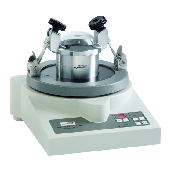
Basic structure Basic structure The PULVERISETTE 0 is equivalent in design to the ANALY‐ SETTE 3 SPARTAN, except that the ANALYSETTE 3 SPARTAN, like the PRO version, also uses a sieve set. Lid (also used in the ANALYSETTE 3 as a clamping lid... -
Page 8: Safety Information And Use
People with health problems or under the influence of medication, drugs, alcohol or exhaustion must not operate this device. The of the PULVERISETTE 0 may only be operated by authorised persons and serviced or repaired by trained specialists. All commissioning, main- tenance and repair work may only be carried out by technically qualified personnel. -
Page 9: Operating Principle
This makes it possible to react to changes in the vibratory system. The amplitude of the PULVERISETTE 0 is set manually with the Plus and Minus key on the control panel and viewed on the lid. 2.3 Obligations of the operator Before using the of the PULVERISETTE 0, this manual is to be carefully read and understood. -
Page 10: Information On Hazards And Symbols Used In This Manual
Safety information and use The of the PULVERISETTE 0 may exclusively be used within the scope of applications set down in this manual and within the framework of guide- lines put forth in this manual. In case of non-compliance or improper... - Page 11 Safety information and use NOTICE! This symbol and keyword combination points out a possibly hazardous situation that can result in property damage if not avoided. ENVIRONMENT! This symbol and keyword combination points out a possibly hazardous situation that can result in environmental damage if not avoided.
- Page 12 Safety information and use WARNING! This symbol and keyword combination points out a directly hazardous situation due to hot surfaces. Ignoring informa- tion with this designation can result in serious burn injuries due to skin contact with hot surfaces. Safety information in the procedure instructions Safety information can refer to specific, individual procedure instruc- tions.
-
Page 13: Device Safety Information
Safety information and use Designation Explanation [Button] Operating elements (e.g. push button, switch), display elements (e.g. signal lamps) ‘Display’ Screen elements (e.g. buttons, function key assignment) 2.5 Device safety information Please observe! Only use original accessories and original spare parts. Failure to observe this instruction can compromise the safety of the machine. -
Page 14: Protective Equipment
European directives and void the guarantee. Only use the of the PULVERISETTE 0 when it is in proper working order, as intended and in a safety- and hazard-conscious manner adhering to the operating manual. In particular, immediately rectify any malfunctions that could pose a safety hazard. -
Page 15: Overload Protection
Safety information and use 2.8.3 Overload protection The mains fuse provides overload protection. - 15 -... -
Page 16: Technical Data
76.6 dB (A) for grinding gravel. The value fluctuates depending on fre- quency, grinding stock and the material of the grinding set. When grinding with the PULVERISETTE 0, the operating noise is greatly reduced by using the sound absorption hood made of plexiglas (order no.: 00.0130.17). -
Page 17: Electrical Fuses
Fuse under mains switch (on the back of the device) Replacement: 4 A M micro fuse, 5 x 20 mm 3.8 Load The maximum load of the PULVERISETTE 0 is up to 6 kg! 3.9 Material Maximum feed size 5 mm Maximum feed quantity 10 ml 3.10... -
Page 18: Installation
The device rests on three flat coil spring assemblies. Level the micro mill: – PULVERISETTE 0: Level the micro mill by screwing these feet in or out so that during grinding, the grinding stock is evenly distributed on the walls of the mortar bowl. -
Page 19: Ambient Conditions
Installation 4.4 Ambient conditions WARNING! Mains voltage! – The device may only be operated indoors. – The surrounding air may not carry any electrically con- ductive dust. – Maximum relative humidity 80% for temperatures up to 31°C, linearly decreasing down to 50% relative humidity at 40°C. -
Page 20: Adjusting The Mains Voltage
Installation 4.5.1 Adjusting the mains voltage CAUTION! Only qualified personnel may change the voltage range on the device! CAUTION! The voltage range may only be adjusted after the mains has been disconnected. CAUTION! If the values 06 or 07 are set at a voltage of 230V~, it will result in a defect in the sieve shaker during operation. -
Page 21: Initial Start-Up
Initial start-up Initial start-up Perform initial start-up only after all work as described in Ä Chapter 4 ‘Installation’ on page 18 has been carried out. 5.1 Switching on The device must be connected to the power supply if this has not been done already. -
Page 22: Using The Device
Using the device Using the device 6.1 Conducting a grinding operation 6.1.1 Parameters Grinding duration 10 ... 30 min (average) Amplitude 1 ... 2 mm (max.) Feed quantity Max. 10 ml (particle feed size ≤ 5 6.1.2 Fitting and clamping the mortar Move the clamping lever on the belt clamping device downwards and insert the toothed belt through the holder from the inside to the outside. -
Page 23: Grinding With Liquid Nitrogen
Using the device The amplitude is set manually with the Plus and Minus key on the con- trol panel and viewed on the lid. (See Ä Chapter 6.3.1 ‘Displaying the amplitude’ on page 25) NOTICE! Do not allow the grinding balls to jump too high. This can cause damage to the lid! Start grinding at low a amplitude and increase it slowly - do not select an amplitude that is too high! (≤... -
Page 24: Setting The Grinding Duration
The grinding elements can then be cooled down enough for grinding to begin. The same must be observed as for normal grinding with the PULVERISETTE 0 as described above. (See Ä Chapter 6.1.2 ‘Fit‐ ting and clamping the mortar’ on page 22). -
Page 25: Setting The Amplitude
The vertical oscillation amplitude can be set in 0.1 mm steps using the + / - keys. Values between 0.1 and 3 mm can be set with the PULVERISETTE 0. NOTICE! Grinding at an amplitude higher than 2 mm can cause damage to the device and the grinding set. -
Page 26: Accessories
(Art. no. 00.0130.17) is available. 7.2 Conversion to Vibratory Sieve Shaker ANALYSETTE 3 SPARTAN The PULVERISETTE 0 can also be used as an ANALYSETTE 3 SPARTAN by using a sieve pan, test sieves and clamping lid. The ANALYSETTE 3 SPARTAN is used to sieve dry bulk solids as well as particle collectives in suspensions. - Page 27 Accessories The sieves are placed onto the sieve pan (with increasingly larger mesh widths, i.e. finest sieve at the bottom) and loosely inserted into one another with seal rings until the sieve set is complete. NOTICE! The sieve mesh width must increase from the bottom to the top.
-
Page 28: Multiple Sieving
Accessories By turning the knurled knobs to the right, tighten the sieve stack evenly until the toothed belts are tightly clamped! If the two toothed belts are not evenly clamped, it is possible that the sieving stock will not be distributed evenly across the sieve surface. -
Page 29: Dry Sieving
Accessories Maximum load: ‐ Sieving stock < 1 kg ‐ Sieves and sieving stock < 6 kg 7.2.2 Dry sieving For dry sieving, use the dry sieve pan (without outlet) and the dry clamping lid (plexiglas clamping lid without nozzles). 7.2.2.1 Sieving parameters Parameters... -
Page 30: Wet Sieving
Accessories 7.2.3 Wet sieving CAUTION! Do not use highly flammable and flammable liquids such as ketones and benzines. For wet sieving, use the wet sieve pan (with outlet and outlet hose) and the wet clamping lid (plexiglas clamping lid with two rotation nozzles). Place the preferably well-dispersed sieving stock (see Ä... -
Page 31: Feeding The Rinsing Liquid
Accessories 7.2.3.3 Feeding the rinsing liquid At the quick-release coupling (N) on the plexiglas clamping lid with 2 rotation nozzles, connect a hose (with hose clamp), through which the rinsing liquid can be fed. Feed just enough water or alcohol (only pos- sible with additional pump) to prevent a backup in the sieve set. -
Page 32: Tips For Wet Sieving Of Difficult Sieving Stock
Accessories 7.2.3.5 Tips for wet sieving of difficult sieving stock For wet sieving of difficult sieving stock, reduce the feed quantity and choose sieves with closely staggered mesh widths. Switch on Interval mode; sieving time: 3...5s (only possible with ANALYSETTE 3 PRO) After the top sieve has sieved completely (is free of fine particles) remove the top sieve after taking off the clamping lid and clamp the clamping lid on the next sieve. -
Page 33: Setting The Sieving Time
Accessories 7.2.5 Setting the sieving time The sieving time can be set in increments of minutes using the +/- keys. Values between 1 and 99 minutes are possible; after a sieving time of 1 hour, let the device cool down. Continuous operation is set by holding down the "-"... -
Page 34: Torquemaster For Easy Clamping Of The Sieve Set
Accessories 7.2.7 TorqueMaster for easy clamping of the sieve set As an alternative to standard clamping devices, the Torque‐ Master can be used for faster and more accurate clamping. TorqueMaster clamping unit with toothed belt Clamping lid Hexagon socket bit (5.5) Cordless screwdriver (with battery and charger) Unclamping aid NOTICE! -
Page 35: Clamping The Torquemaster
Accessories The starting position of the clamping system is the position at which both indicators are roughly in the centre of the respective display range. This position later ensures that sieve stacks of various heights can be clamped easily, or that there is sufficient space to release the system, remove it from the sieve stack and place it behind the device. - Page 36 (cordless screwdriver). This disengage- ment torque must be set by the clamping system manufacturer. Thus other cordless screwdrivers, which were not set by Fritsch, must not be used. If cordless screwdrivers with too high a torque are used, it will cause irreparable damage to the clamping system for which no liability can be assumed.
-
Page 37: Releasing The Torquemaster
Accessories 7.2.7.3 Releasing the TorqueMaster The TorqueMaster clamping device is also released with the cordless screwdriver. The clamping unit is released far enough so that it can be placed behind the device without changing the toothed belt clamp in the belt clamping device. -
Page 38: Maintenance Of The Torquemaster Clamping Device
Accessories 7.2.7.6 Maintenance of the TorqueMaster clamping device The clamping unit is largely maintenance-free. Cleaning with standard solvent-free cleaning agents is permissible. The clamping unit is closed to a large extent. Make sure that as little liquid, dust, dirt or other foreign bodies as possible enters the clamping unit through the outlets for the toothed belts. -
Page 39: Cleaning
Cleaning Cleaning DANGER! Mains voltage! – Before beginning with cleaning work, disconnect the mains plug and protect the device against being unin- tentionally switched back on! – Do not allow any liquids to flow into the device. – Indicate cleaning work with warning signs. –... - Page 40 Cleaning NOTICE! The plexiglas lid must not be cleaned with alcohol or organic solvents. - 40 -...
-
Page 41: Maintenance
Maintenance Maintenance DANGER! Mains voltage – Before beginning with maintenance work, unplug the mains plug and protect the device against being unin- tentionally switched back on again! – Indicate maintenance work with warning signs. – Maintenance work may only be performed by special- ised personnel. -
Page 42: Repairs
Repairs Repairs DANGER! Mains voltage! – Before beginning with repair work, unplug the mains plug and protect the device against being unintention- ally switched back on. – Indicate repair work with warning signs. – Repair work may only be performed by specialised per- sonnel. -
Page 43: Disposal
FRITSCH declares it is prepared to take back used FRITSCH devices for recycling or disposal free of charge whenever a new device is purchased. The used FRITSCH device must be delivered free of charge to a FRITSCH establishment. In all other cases FRITSCH takes back used FRITSCH devices for recycling or disposal only against payment. -
Page 44: Guarantee Terms
Guarantee terms Guarantee period As manufacturer, FRITSCH GmbH provides – above and beyond any guar- antee claims against the seller – a guaranty valid for the duration of two years from the date of issue of the guarantee certificate supplied with the device. - Page 45 Any servicing done by persons not authorised by us and any use of parts that are not original FRITSCH accessories and spare parts will void the guar- antee.
- Page 46 FRITSCH GMBH distributor or Fritsch GmbH, Industriestr. 8, D-55743 Idar-Oberstein. FRITSCH GMBH takes the greatest care to ensure that the quality, relia- bility and safety of your products are continuously improved and adapted to the state of the art. The supplied products as well as this operating manual conform to the current state of the art when they leave the sphere of influence of FRITSCH GMBH.
- Page 47 Exclusion of liability Fritsch GmbH excludes any liability, warranty, or other obligation to com- pensate for damages, regardless of whether this liability, warranty, or other obligation is explicit or implicit, contractual or arising from unlawful acts or prescribed contractually, by law, or otherwise. In no...
- Page 48 Safety logbook Safety logbook Date Maintenance / Repair Name Signature - 48 -...
- Page 49 Safety logbook Date Maintenance / Repair Name Signature - 49 -...
- Page 50 Index Index Maximum load ......17 Mortar Accident prevention ......8 Clamping .
- Page 52 © 2014 Fritsch GmbH Milling and Sizing Industriestraße 8 D - 55743 Idar-Oberstein Telephone: +49 (0)6784/ 70-0 Fax: +49 (0)6784/ 70-11 email: info@fritsch.de Internet: www.fritsch.de...
Need help?
Do you have a question about the PULVERISETTE 0 and is the answer not in the manual?
Questions and answers