Table of Contents
Advertisement
Quick Links
Advertisement
Table of Contents

Subscribe to Our Youtube Channel
Related Manuals for Major tech MT332


Summary of Contents for Major tech MT332
- Page 1 INSTRUCTION MANUAL MT332 EARTH RESISTANCE CLAMP METER...
-
Page 3: Table Of Contents
Contents Page no 1. Introduction..................4 2. Safety Rules and Precautions ..............5 3. Instrument Structure.................5 4. LCD ....................6 4.1. Description of special symbols............6 5. Principal of Resistance Measurement...........7 6. Operation..................7 6.1. Power Function.................7 6.2. Battery Voltage Check..............8 6.3. Earth Resistance and Leakage Current Test........8 6.4. -
Page 4: Introduction
Built with a shock-proof, dust-proof, and moisture-proof structure, the MT332 is well-suited for demanding environments. It is an essential tool in telecommunications, electricity, metrology, computer rooms, oil fields, and electromechanical installation and maintenance within industrial enterprises utilizing electricity as power or energy source. -
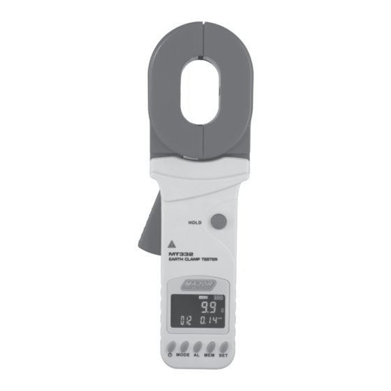
Page 5: Instrument Structure
period of time. Ÿ When the meter displays battery low voltage symbol " “ put the meter on charge immediately, otherwise it will lead to measurement errors. Ÿ Turn off the meter when replacing the battery. Ÿ The contact surface of the jaws must be kept clean and cannot be wiped with corrosives and rough objects. -
Page 6: Lcd
4. LCD 1 - Clamp head open symbol. 2 - Alarm indication symbol 3 - Greater than symbol 4 - AC and DC indication symbols 5 - Data access symbols 6 - Data storage symbols 7 - Noise indicator symbol 8 - Data lock symbol 9 - Battery level indicator 10 - Unit indication... -
Page 7: Principal Of Resistance Measurement
5. PRINCIPLE OF RESISTANCE MEASUREMENT The basic principle of the Clamp-On Earth Resistance Tester is to measure earth resistance and the leakage current in the loop. (See below figure 1). The clamp jaw is composed of a voltage coil and a current coil. The voltage coil provides the excitation signal and induces a potential voltage (V) on the loop under test. -
Page 8: Battery Voltage Check
6.2. Battery Voltage Check When switching on the clamp meter and the LCD displays the low battery voltage symbol " ", it means the battery is low, please replace the battery. The battery power must be sufficient to ensure the accuracy of the measurement. -
Page 9: Alarm System
6.4. Alarm System When switching on the clamp meter, short press the "AL" key to turn the alarm function on or off. Long press the "SET" key to set the resistance, current, and voltage alarm values. To change the current number, press the "AL"... -
Page 10: Data Storage / Review / Deletion
6.6. Data Storage / Review / Deletion When the measurement is completed after switching on the clamp meter, short press the "HOLD" key to store the data. The "MEM" symbol will flash and automatically number. If the storage is full, the meter will flash the "MEM"... -
Page 11: Limited Point Earthing System
When measured with a clamp meter, its equivalent circuit is as follows: "R1" is the predicted earth resistance. "R0" is the equivalent resistance of the earthing resistances of all other towers in parallel. Although, from the strict earthing theory, due to the existence of the so-called "mutual resistance", "R0"... -
Page 12: Single Point Earthing System
manually, and it is even impossible when "N" is large. In addition to ignoring mutual resistance, this method does not have the measurement error caused by ignoring "R0". However, users need to pay attention to this, in your earthing system, there are several earthing bodies connected to each other, and the same number of test values must be measured for the program to solve, not more or less. - Page 13 The second step is to connect "RB" and "RC" as shown in the figure below. Use the clamp meter to read the second data "R2". The third step is to connect "RC" and "RA" as shown in the figure below. Use the clamp meter to read the third data "R3".
-
Page 14: Specifications
The earthing resistance values of the other two earthing bodies as reference objects are: "RB" = "R1" – "RA" "RC" = "R3" – "RA" 9. SPECIFICATIONS 9.1. Model parameters Model Resistance Range Current Range MT332 0.01Ω-1200Ω 0.00mA-20A 9.2. Range and Accuracy Measuring function Measuring Range Resolution Accuracy 0.010Ω - 0.099Ω... -
Page 15: Technical Specifications
The contents of this user manual cannot be used as a reason for using the product for special Meter 1 pc purposes. Major Tech is not responsible for other Battery 4 AA Batteries losses caused by use. Major Tech reserves the... - Page 16 MAJOR TECH (PTY) LTD South Africa Australia www.major-tech.com www.majortech.com.au sales@major-tech.com info@majortech.com.au...
Need help?
Do you have a question about the MT332 and is the answer not in the manual?
Questions and answers