Table of Contents
Advertisement
Quick Links
Advertisement
Table of Contents

Related Manuals for Major tech MT957


Summary of Contents for Major tech MT957
- Page 1 INSTRUCTION MANUAL MT957 LCR Meter...
-
Page 3: Safety Information
SAFETY INFORMATION The following safety information must be observed to insure maximum personal safety during the operation of this meter: Do not use the meter if the meter or test leads look damaged, or if Ÿ you suspect that the meter is not operating properly. Never ground yourself when taking electrical measurements. - Page 4 Safety This symbol adjacent to another symbol, terminal or operating device indicates that the operator must refer to an explanation in the Operating Instructions to avoid personal injury or damage to the meter. This symbol adjacent to one or more terminals identifies them as being associated with ranges that may, in normal use, be subjected to particularly hazardous voltages.
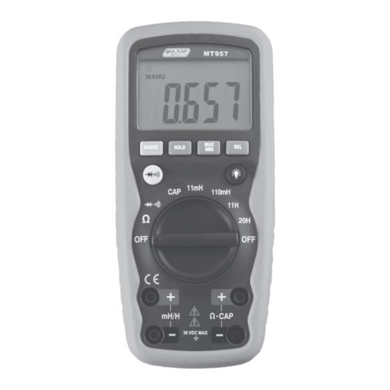
- Page 5 Controls and jacks 11000 count Liquid Crystal Display Function switch Positive input jack for inductance measurements Negative input jack for inductance measurements Positive input jack COM (Negative) input jack. Diode pushbutton RANGE pushbutton HOLD pushbutton 10. MAX/MIN pushbutton 11. Relative Zero pushbutton 12.
-
Page 6: Specifications
Symbols and Annunciators Continuity Low Battery Diode HOLD Data Hold AUTO Auto Ranging MANUAL Manual Ranging SPECIFICATIONS The instrument complies with: EN61010-1 Insulation: Class 2, Double insulation Overvoltage category: CATIII 600V Display: 11000 counts LCD display with function indication. Polarity: Automatic, (-) negative polarity indication. - Page 7 For inside use, max height: 2000m Power: One 9V battery , NEDA 1604, IEC 6F22. Dimensions: 150 (H) x 70 (W) x 48 (D) mm Weight: Approx.: 255g. Accuracy is given at 18 °C to 28 °C (65 °F to 83 °F), less than 70 % RH Resistance Range Resolution...
-
Page 8: Operation
Inductance (Manual-ranging) Range Resolution Accuracy 11.000mH ±2.0% of rdg ±0.05mH 110.00mH 10uH ±5.0% of rdg ± 0.05H 11.000H ±5.0% of rdg ± 0.2H 20.00H 10mH Maximum Input: 600V DC or 600V AC RMS Diode Test Test current Resolution Accuracy 0.3mA typical ±10% of rdg ±... -
Page 9: Auto Ranging/Manual Range Selection
AUTO RANGING/MANUAL RANGE SELECTION When the meter is first turned on, it automatically goes into Auto ranging. This automatically selects the best range for the measurements being made and is generally the best mode for most measurements. For measurement situations requiring that a range be manually selected, perform the following: Press the RANGE key. -
Page 10: Display Backlight
DISPLAY BACKLIGHT The BACK LIGHT BUTTON is used to turn the back light ON. Push the BACK LIGHT BUTTON again to turn the back light OFF. HOLD: The hold function freezes the reading in the display. Press the HOLD key momentarily to activate or to exit the HOLD function. -
Page 11: Diode Test
DIODE TEST WARNING: To avoid electric shock, do not test any diode that has voltage on it. Set the function switch to position. Press the button until the symbol appears in the display. Insert the black test lead banana plug into the negative (-) jack (COM) and the red test lead banana plug into the positive (+) jack (Ω). -
Page 12: Inductance Measurement
INDUCTANCE MEASUREMENT WARNING: To avoid electric shock, disconnect both test probes from any source of voltage before making a inductance measurement. If you wish to measure inductance, set the function switch to the 10mH. Insert the black test lead banana plug into Negative input jack for inductance measurements and the red test lead banana plug into Negative input jack for inductance measurements. -
Page 13: Battery Installation
BATTERY INSTALLATION WARNING: To avoid electric shock, disconnect the test leads from any source of voltage before removing the battery door. Disconnect the test leads from the meter. Open the battery door by loosening the screw using a Phillips head screwdriver. - Page 16 MAJOR TECH (PTY) LTD South Africa Australia www.major-tech.com www.majortech.com.au sales@major-tech.com info@majortech.com.au...
Need help?
Do you have a question about the MT957 and is the answer not in the manual?
Questions and answers