Table of Contents
Advertisement
Quick Links
Advertisement
Table of Contents

Related Manuals for Major tech MT723


Summary of Contents for Major tech MT723
- Page 1 INSTRUCTION MANUAL MT723 AC/DC TRMS CLAMP METER...
-
Page 3: Table Of Contents
Contents Page no 1. Safety ..................4 1.1. lnternational Safety Symbols ..........4 1.2. SAFETY NOTES ............. .4 1.3. WARNINGS ..............4 1.4. CAUTIONS ............... 4 2. lnput Limits ................5 3. Meter Description ..............5 4. Symbols Used on LCD Display ..........6 5. -
Page 4: Safety
1. Safety 1.1. lnternational Safety Symbols This symbol, adjacent to another symbol or terminal, indicates the user must refer to the manual for further information. This symbol, adjacent to a terminal, indicates that, under normal use,hazardous voltages may be present. Double insulation. -
Page 5: Lnput Limits
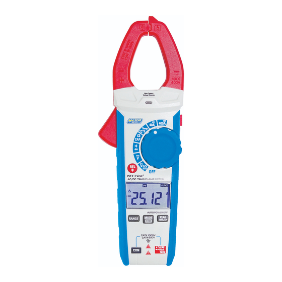
2. Input Limits Function Maximum Input A AC/DC 400A V AC/DC 1000V DC/AC Resistance, Capacitance, 300V DC/AC Frequency, Diode Test, Temperature 3. Meter Description NCV Test COM input jack Current clamp Data Hold and Backlight button Non-contact AC voltage 10. Rotary Function switch indicator light 11. -
Page 6: Symbols Used On Lcd Display
4. Symbols Used on LCD Display Data Hold Negative reading display Measurement display digits REL/DCA Zero Maximum/Minimum Auto Power Off Auto Range mode Direct Current / Voltage Alternating Current Voltage Low battery Milli-volts or Volts (Voltage) (Resistance) Amperes (Current) Farad (Capacitance) Hertz (Frequency)/Percent (duty ratio) Fahrenheit and Celsius units (Temperature) Unit of measure prefixes: nano, milli, micro, mega, and kilo... -
Page 7: Specifications
5. Specifications Range Resolution Accuracy ±(% of reading+digits) Function 40.00A 10mA ±(2.0% + 8 digits) AC True RMS Current 100mA 400.0A ±(2.5% + 8 digits) Over range protection: Maximum input 400A. Accuracy specified from 5% to 100% of the measuring range. Frequency Response: 50Hz to 60Hz True RMS. - Page 8 Range Resolution Accuracy ±(% of reading+digits) Function 99.99nF* 0.01nF ±(4.5% + 20 digits) Capacitance 0.1nF (Auto-ranging) 999.9nF 0.001µF 9.999µF ±(3.0% + 5 digits) 0.01µF 99.99µF 0.1µF 999.9µF 0.001mF 9.999mF ±(5% + 5 digits) 0.01mF 99.99mF Input Protection: 300V DC or 300V AC RMS. * <...
-
Page 9: General Specifications
6. General Specifications Clamp jaw opening 30mm approx. Display 3-3/4 digits (4000 counts) backlit LCD Low Battery indication ‘ ' is displayed Over-range indication 'OL' display Measurement rate 3 readings per second, nominal Temperature sensor Type K thermocouple Input Impedance 10M (VDC and VAC) AC response True RMS (AAC and VAC) -
Page 10: Operation
7. Operation NOTES: Read and understand all Warning and Caution statements in this operation manual prior to using this meter. Set the function select switch to the OFF position when the meter is not in use. 7.1. AC/DC Current Measurements WARNING: Ensure that the test leads are disconnected from the meter before making current clamp measurements. -
Page 11: Ac Voltage Measurement
7.2. AC Voltage Measurement 1.lnsert the black test lead into the negative COM terminal and the red test lead into the positive V CAP·TEMP·Hz% Ω terminal. 2. Set the function switch to the V~ position. 3. Press the MODE/VFD key for 1 second to turn on the VFD test. 4. -
Page 12: Resistance
7.6. Resistance 1. lnsert the black test lead into the negative COM terminal and the red test lead into the V CAP TEMP Hz% positive terminal. 2. Set the function switch to the Ω position. 3. Touch the test probe tips across the circuit or component under test. 4. -
Page 13: Continuity Measurements
7.9. Continuity Measurements 1. lnsert the black test lead into the negative COM terminal and the red test lead into the V CAP TEMP Hz% Ω positive terminal. 2. Set the function switch to the Ω position. 3. Use the MODE button to select continuity " ". The display icons will change when the MODE button is pressed. -
Page 14: Range
7.13. RANGE Press the RANGE key to activate the manual mode and to disable the Autorange function. The symbol "AUTO" disappears from the upper left part of the display. In manual mode, press the RANGE key to change measuring range: the relevant decimal point will change its position. The RANGE key is not active in positions , CAP, Hz%,Temp °C °F. -
Page 15: Maintenance
8. Maintenance WARNING: To avoid electrical shock, disconnect the meter from any circuit, remove the test leads from the input terminals, and turn OFF the meter before opening the case. Do not operate the meter with an open case. 9. Cleaning and Storage 1. - Page 16 MAJOR TECH (PTY) LTD South Africa Australia www.major-tech.com www.majortech.com.au sales@major-tech.com info@majortech.com.au...
Need help?
Do you have a question about the MT723 and is the answer not in the manual?
Questions and answers