Table of Contents
Advertisement
Quick Links
Advertisement
Table of Contents

Related Manuals for Major tech MT975


Summary of Contents for Major tech MT975
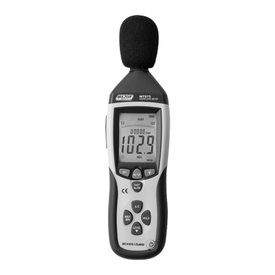
- Page 1 INSTRUCTION MANUAL MT975 SOUND LEVEL METER...
-
Page 2: Safety Information
SAFETY INFORMATION Read the following safety information carefully before attempting to operate or service the meter. Use the meter only as specified in this manual: Environment conditions ① Altitude lower than 2000 meters ② Relatively humidity ≤90%RH ③ Operation Ambient 0 ~ 40°C ... -
Page 3: Specification
Under range display A & C Weighting FAST & SLOW response Analog AC/DC outputs for connection to frequency analyzer or X-Y shaft recorder 3. SPECIFICATION Standard applied: IEC61672 -1 CLASS2 Accuracy:±1.4dB Frequency range:31.5HZ ~ 8KHZ Dynamic range:50dB Memory:32700 Level ranges: LO:30dB~80dB Med:50dB~100dB... -
Page 4: Name And Functions
Data output: USB data traffic Auto power off:Meter automatically shuts down after approx. 15 minutes of inactivity. Power supply: One 9V battery, 006P or NEDA1604 or IEC 6F22. Power life: About 30hours Operation temperature and humidity: 0°C~40°C,10%RH~90%RH Storage temperature and temperature: -10°C ~+60°C,10%RH~75%RH Dimension: 278 (L) x 76 (W) x 50(H) mm Weight : 350g... - Page 5 ② LCD: SYMBOL FUNCTION 4 digits Maximum hold Minimum hold OVER over range UNDER under range FAST Fast response SLOW Slow response A-Weighting(responseto human sense) C-Weighting(response to machine monitor) 30—130 Range indicate Recording data into computer AUTO Auto level range selection FULL Memory full HOLD...
- Page 6 ③REC button 3.0 DATALOGGER function Press “REC” button once the power has been switched on, the display will show “REC” to start Data Recording,press the button again to exit the record (Note: In order to avoid data error, please don’t power it off under REC condition, when the REC function is deleted then it can power off).
- Page 7 Press‘SETUP’button and then power it on,when‘TIME’ symbol displays then loosen‘SETUP’ ,the meter will be under time adjustment mode,at the time the display will show the date as following: Select the‘SETUP’button for a second time, the ‘hour adjustment mode will be displayed: Select ‘LEVEL’...
- Page 8 Press the‘SETUP’button for a fourth time, the ‘date’ adjustment mode will be displayed Press ‘LEVEL’ to make the adjustment,press ‘HOLD’ to keep the setup; Press the ‘SETUP’ button for a fifth time, the ‘month’ adjustment mode will be displayed: Press ‘LEVEL’...
- Page 9 adjustment mode will be displayed: Press ‘HOLD’ to save the setup. The time and date will return to the factory setup once the battery is flat or needs to be replaced, if the time can’t be adjusted, initialize the time chip first.
- Page 10 time to exit MAX/MIN measurement. ⑦LEVEL button: Level range selection Each time you press “LEVEL” button, the level range will change between ‘Lo’ level, ‘Med’ level, ‘Hi’ level and ‘Auto’ level in that sequence. Backlight button ⑧ 8.0.Turn the backlight on/off 8.1.DATALOGGER response setting;...
- Page 11 Turn the meter power ON/OFF ⑿ External DC 9V power supply terminal 1 x DC 9V power supply. Aperture size: external diameter: 3.5mm internal diameter: 1.35mm ⒀ USB interface USB signal output is a 9600 bps serial interface. ⒁ AC/DC signal output earphone outlet OUTPUT OUTPUT GROUND...
-
Page 12: Calibration Procedures
⒃ Tripod mounting screw ⒄ Battery cover ⒅ Microphone 1/2 inch Electret Condenser microphone ① CALIBRATION PROCEDURES Make the following switch settings: Frequency weighting: A-weighting Time weighting: FAST Level range: 50 ~100dB ② Insert the microphone housing carefully into the 1/2 inch insertion hole of the calibrator(94dB @ 1kHZ). -
Page 13: Measurement Preparation
MEASUREMENT PREPARATION ① Remove the battery cover on the back and insert one 9V battery. ② Replace the back cover. ③ The symbol will appear on the LCD screen when the battery voltage drops below the operating voltage and once the battery is flat. ④... - Page 14 battery to avoid battery liquid leakage and damage to the instrument. iii. When using the instrument in the presence of wind, it is essential to mount the wind absorber to avoid undesirable signals. iv. Keep the microphone dry and avoid sever vibration. 9.
- Page 15 added to the Ports in the Device Manager. Port number will be ranged following the primary COM ports, such as: COM3 or COM4. Once the drive software is installed, start the application software, connect the meter to the computer with the USB, then search for the COMX port occupied by CP210X, press button, The ‘...
- Page 16 The computer reads the memory data in the meter when REC mode does not appear on the display and the connection is in order.
Need help?
Do you have a question about the MT975 and is the answer not in the manual?
Questions and answers