
Related Manuals for Major tech MT784


Summary of Contents for Major tech MT784
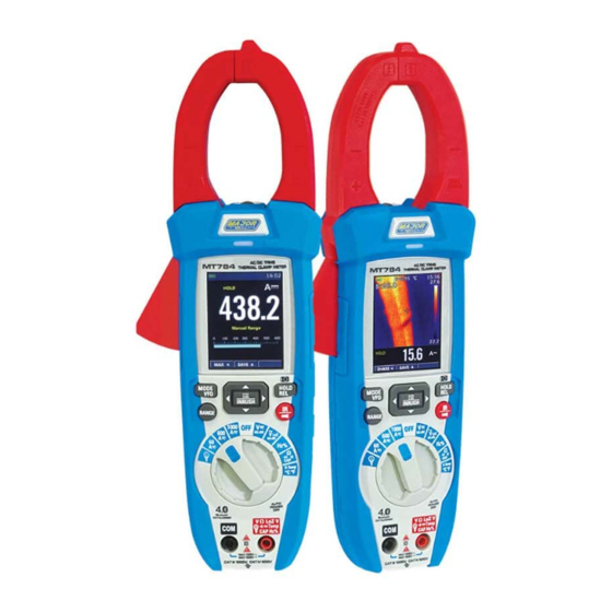
- Page 1 INSTRUCTION MANUAL MT784 1500V DC THERMAL CLAMP METER WITH DATA LOGGER & MOBILE APP...
-
Page 3: Table Of Contents
Contents Page no 1. Introduction ..................5 2. Safety ..................... 5 2.1. Safety Information..............5 2.2. Per IEC1010 Overvoltage Installation Category......6 2.3. Safety Instructions..............6 3. Description ..................7 3.1. Meter Description..............7 3.2. Understanding the Push Buttons..........8 3.2.1. Cursor Buttons..............8 3.2.2. Physical Buttons..............8 3.3. - Page 4 Contents Page no 5.3. Using the Clamp Meter with the Thermal Imager......28 5.3.1. Capturing MAX/MIN Values on IR+Clamp Meter Mode..28 5.3.2. Capturing Peak Values on IR+Clamp Meter Mode....29 6. Settings Menu..................29 6.1. Using Settings Menu..............29 6.2. Settings Details................29 6.2.1. Palette Mode..............29 6.2.2.
-
Page 5: Introduction
1. INTRODUCTION The MT784 is a CAT IV 600V True RMS 1000A AC/DC digital clamp meter incorporating an 80 x 80 pixel Thermal Imager with a range from -20°C to 260°C. This clamp meter has a large 6000 count colour TFT LCD display that provides fast sampling times and high accuracy measurements. -
Page 6: Per Iec1010 Overvoltage Installation Category
safety, the meter and its test leads should not be handled when these terminals are energized. This symbol indicates that a device is protected throughout by double insulation or reinforced insulation. 2.2. Per IEC1010 Overvoltage Installation Category Overvoltage Category I Equipment of OVERVOLTAGE CATEGORY I is equipment for connection to ciruits in wchich measures are taken to limit the transient overvoltages to an appropriate low level. -
Page 7: Description
• Use extreme caution when working with high voltages. • Do not measure voltage if the voltage on the “COM” input jack exceeds 1000V above earth ground. • Never connect the meter leads across a voltage source while the function switch is in the current, resistance or diode mode, doing so can damage the meter. -
Page 8: Understanding The Push Buttons
3.2. Understanding the Push Buttons The 9 push buttons on the front of the Meter activate features that augment the function selected using the rotary switch, navigate menus or control power to Meter circuits. 3.2.1. Cursor Buttons: Select an item in a menu, adjust display contrast, scroll through information, and perform data entry. -
Page 9: Icons On Lcd Display
3.3.2. Icons on LCD Display Voltage is over 30V (AC or DC) AC Voltage or Current Warming DC Voltage or Current Flexible Coils AC+DC Voltage or Current Traditional Clamps Continuity Function Relative Diode Function High Edge Time Ohms Variable Frequency Driver VFD Loz Low Impedance Mode Inrush Current 3.4. -
Page 10: Clamp Meter Measurement And Setup
4. CLAMP METER MEASUREMENT AND SETUP 4.1. DC Voltage Measurement CAUTION: Do not measure DC voltages if a motor on the circuit is being switched ON or OFF, Large voltage surges may occur that can damage the meter. 1. Set the function switch to the V Position. -
Page 11: Ac+Dc Voltage Measurement
4.2. AC+DC Voltage Measurement CAUTION: Do not measure DC voltages if a motor on the circuit is being switched ON or OFF, Large voltage surges may occur that can damage the meter 1. Set the function switch to the V Position. -
Page 12: Ac Voltage Measurement
4.3. AC Voltage Measurement WARNING: Risk of Electrocution. The probe tips may not be long enough to contact the live parts inside some 240V outlets for appliances because the contacts are recessed deep in the outlets. As a result, the reading may show 0 volts when the outlet actually has voltage on it. -
Page 13: Frequency Measurement
4.4. Frequency Measurement 1. Set the function switch to the Hz% Position. 2. Insert the black test lead banana plug into the negative COM jack. 3. Insert the red test lead banana plug into the Positive jack. 4. Read the Frequency in the display. 5. -
Page 14: Loz Ac Voltage Measurement
4.5. LoZ AC Voltage Measurement WARNING: Risk of Electrocution. The probe tips may not be long enough to contact the live parts inside some 240V outlets for appliances because the contacts are recessed deep in the outlets. As a result, the reading may show 0 volts when the outlet actually has voltage on it. -
Page 15: Resistance Measurement
4.6. Resistance Measurement WARNING: To avoid electric shock, disconnect power to the unit under test and discharge all capacitors before taking any resistance measurements, remove the batteries and unplug the line cords. 1. Set the function switch to the Ω CAP Position. -
Page 16: Continuity Check
4.7. Continuity Check WARNING: To avoid electric shock, disconnect power to the unit under test and discharge all capacitors before taking any resistance measurements, remove the batteries and unplug the line cords. 1. Set the function switch to the Ω CAP Position. -
Page 17: Diode Test
4.8. Diode Test 1. Set the function switch to the Ω CAP Position. 2. Insert the black test lead banana plug into the negative COM jack. 3. Insert the red test lead banana plug into the Positive jack. 4. Press the MODE key to switch the Diode functions. •... -
Page 18: Capacitance Measurement
4.9. Capacitance Measurement WARNING: To avoid electric shock, disconnect power to the unit under test and discharge all capacitors before taking any resistance measurements, remove the batteries and unplug the line cords. 1. Set the function switch to the Ω CAP Position. -
Page 19: Temperature Measurement
4.10. Temperature Measurement 1. Set the function switch to the Temp °C°F Position. 2. Insert the Temperature Probe into the input jacks, making sure to observe the correct polarity. 3. Read the Temperature on the display. 4. Press the MODE key to switch the Unit (°C or °F). -
Page 20: Flexible Coil Current Measurement
4.11. Flexible Coil Current Measurement (MT740 Optional) 1. Set the function switch to the Flexible Coil Position. 2. Insert the black test lead banana plug into the negative COM jack. 3. Insert the red test lead banana plug into the Positive jack. 4. -
Page 21: Dc Clamp Current Measurement
4.12. DC Clamp Current Measurement 1. For current measurements up to 60A DC, set the function switch to the 60A Position. 2. For current measurements up to 600A DC, set the function switch to the 600A Position. 3 For current measurements up to 1000A DC, set the function switch to the 1000A Position. -
Page 22: Ac Clamp Current Measurement
4.13. AC Clamp Current Measurement 1. For current measurements up to 60A AC, set the function switch to the 60A Position. 2. For current measurements up to 600A AC, set the function switch to the 600A Position. 3 For current measurements up to 1000A AC, set the function switch to the 1000A Position. -
Page 23: Inrush Current Measurement
4.14. Inrush Current Measurement 1. Set the function switch to the 60A or (600A ,1000A) Position. 2. Press the INRUSH Button (Enter key 2 second) to indicate “ ” on the display, Then measurement display “----”. 3. Clamp the cable to be motor. 4. -
Page 24: Vfd Mode
4.15. VFD Mode 1. Set the function switch to the 60A or (600A, 1000A) Position to AC Current measurement, or switch to the V Position to AC Voltage measurement. 2. Press the MODE/VFD Button (2 second) to indicate “VFD” on the display, to variable frequency driver measurements. -
Page 25: Relative Values
4.18. Relative Values • REL key can be used as the “ZERO” function of DC current as well as relative value measurement of other functions. • Hold down the HOLD/REL key to enter REL function. • Hold down this key to quit REL. 4.19. -
Page 26: Thermal Imager And Clamp Meter Operation
Notes: The detector is designed with high sensivity, static electricity and other sources of electrical energy may randomly activate the detector. This is normal operation, the detector only activates the indicator light when AC voltage is present, it does not indicate the voltage level on the LCD display. 5. -
Page 27: Using The Thermal Imager
5.2. Using the Thermal Imager For basic operation follow these steps: 1. Set the function switch to any position. 2. Press the “IR” button to switch the thermal imager ON, Target the object by the thermal imager lens. 3. The display will show the temperature measurement in the upper left hand corner for the targeted area along with the currently selected Emissivity value. -
Page 28: Using The Clamp Meter With The Thermal Imager
5.3. Using the Clamp Meter with the Thermal Imager On IR+Clamp Meter mode, MODE key, RANGE key, HOLD key and REL Function is the same in Clamp Meter mode. 5.3.1. Capturing MAX/MIN Values on IR+Clamp Meter Mode 1. To activate the maximum in mode, press the “... -
Page 29: Capturing Peak Values On Ir+Clamp Meter Mode
5.3.2. Capturing Peak Values on IR+Clamp Meter Mode 1. To activate the peak mode, press the “ ” key to display the Peak max value. 2. If the Meter is already in peak function, then press the “ ” key to display Peak min value, then press the “... -
Page 30: Temp Unit
6.2.2. Temp Unit • Press RIGHT/MENU button to set focus on this option and the colour of option value will change to black °C. • In focus state, use the RIGHT/MENU Button to toggle °C, °F and K, use LEFT/RIGHT/MENU button to exit focus state and the colour of option value will change white K. -
Page 31: Language
6.2.5. Language • Press RIGHT/MENU Button to enter the language menu. • Three options are available: Simplified Chinese, Traditional Chinese and English. • Use UP/DOWN Button to select language and use RIGHT/MENU Button to set selected language to be valid. 6.2.6. -
Page 32: Bluetooth Connect
6.2.7. Bluetooth Connect 1. Turn on the Bluetooth function on the instrument. 2. Turn on the bluetooth of the smart phone, press the icon Thermview+ and enter into the home interface, then press Connect Device icon on the Home interface, bluetooth device name will appear. -
Page 33: Time/Date
6.2.8. Time/Date • Press the RIGHT/MENU Button to enter time menu. • In this menu, year, month, day, hour, minute and time format can be set. • The changes take effect after exiting settings menu. 6.2.9. Photo • Press the RIGHT/MENU Button to enter photo menu. -
Page 34: System Info
6.2.10. System Info • Press the RIGHT/MENU Button to enter system information menu. • This menu contains the software version, hardware version and thermal imager version. 6.2.11. Factory Set • When selecting the Factory Set option, after pressing the RIGHT/MENU button, a dialog box will be displayed as shown. -
Page 35: Record Measurements
6.3. Record Measurements • With a measurement on the display, press the Menu key to enter the instrument’s general menu. • The screen is shown on the display, press the Button “ ” or “ ” key to select record Item. •... - Page 36 • In Record Menu, press the Button “ ” or “ ” key to select Start record Item. • Press the Button “ ” Enter Save Record measurement. • In Save Record measurement, Press the Button “ ” to stop record and Press the Button “...
-
Page 37: Image Browser
• In Record View Display, press the “ ” or “ ” key to move the cursor on the graph. • And the button “ ” to activate the Zoom function of the graph, increasing resolution (symbol “Zoom Xy” where y=max zoom dimension appears at the top of the display on the right side). -
Page 38: How To Capture A Screen
7.1. How to Capture a Screen • When in clamp meter mode or thermal imaging+clamp meter mode, use the HOLD button to enter hold mode, as shown below. • Then press the UP Button to capture screen. • After saving to TF card completely, Clamp Meter will exit hold mode. -
Page 39: Specifications
8. SPECIFICATIONS 8.1. General Specifications Basic Functions Range Reference Standards Safety IEC/EN61010-1 IEC/EN 61326-1 Insulation Double Insulation Pollution Level Overvoltage Category CAT IV 600V, CAT III 1000V Max Operating Altitude 2000m (6562ft) Power Supply Battery Type 1 x 7.4V Rechargeable Li-ion Battery, 1200mAh Battery Charger Power Supply 100/240VAC, 50/60Hz, 12VDC, 2A... -
Page 40: Thermal Imager Specifications
8.2. Thermal Imager Specifications Function Range Field of View (FOV)/ 21° x 21°/0.5m Minimum Focus Distance Spatial Resolution (IFOV) 4.53mrad IR Resolution 80 x 80 pixels Thermal Sensitivity/NETD <0.1°C at 30°C (86°F)/100mK Image Frequency 50Hz Focus Mode Focus free Focal Length 7.5mm Focal Plane Array (FPA)/ Uncooled microbolometer/8-14μm... -
Page 41: Ac Trms Voltage
8.3.2. AC TRMS Voltage Range Resolution Accuracy 6.000V 0.001V 50Hz-60Hz: ±(1.2% + 5 digits) 60.00V 0.01V 61Hz-1kHz: ±(2.5% + 5 digits) 600.0V 0.1V 1000V Protection against overcharge: 1000VDC/ACrms. Accuracy specified from 10% to 100% of the measuring range, sine wave; Input impedance: >... -
Page 42: Dc Current
8.3.6. DC Current Range Resolution Accuracy 60.00A 0.01A 600.0A 0.1A ±(2.0% + 8 digits) 1000A Protection against overcharge: 1000ADC/ACrms. 8.3.7. AC TRMS Current Range Resolution Accuracy 60.00A 0.01A 600.0A 0.1A 50Hz-60Hz: ±(2.5% + 5 digits) 1000A Protection against overcharge: 1000ADC/ACrms. Accuracy specified from 10% to 100% of the measuring range, sine wave. -
Page 43: Frequency (Electronic Circuits)
8.3.11. Frequency (Electronic Circuits) Range Resolution Accuracy 60.00Hz 0.01Hz 600.0Hz 0.1Hz 6.000kHz 0.001kHz 60.00kHz 0.01kHz ±(0.2% + 5 digits) 600.0kHz 0.1kHz 6.000MHz 0.001MHz 10.00MHz 0.01MHz Protection against overcharge: 1000VDC/ACrms. Sensitivity: >2Vrms (at 20%-80% duty cycle) and f<100kHz; >5Vrms (at 20%-80% duty cycle) and f>100kHz. 8.3.12. - Page 44 MAJOR TECH (PTY) LTD South Africa Australia www.major-tech.com www.majortech.com.au sales@major-tech.com info@majortech.com.au...
Need help?
Do you have a question about the MT784 and is the answer not in the manual?
Questions and answers