YASKAWA GA500 Technical Manual
Hide thumbs
Also See for GA500:
- Programming (526 pages) ,
- Maintenance & troubleshooting (292 pages) ,
- Installation and operation instruction manual (81 pages)
Advertisement
Quick Links
This supplemental technical manual describes the modified specifications with a GA500 software upgrade and
corrections. Read this manual together with " Installation & Primary Operation" (TOEP C710617 52) included with
the product and the " GA500 Technical Reference" (SIEP C710617 52) that you can download from our
documentation website. Read and understand the safety information and precautions before you start to use the
product.
Item
Setting range of C6-02 [Carrier Frequency Selection] when in
1.
AOLV/PM
Addition of Parameter Not Initialized when A1-03 = 2220, 3330
2.
[Initialize Parameters = 2-Wire Initialization, 3-Wire Initialization]
3.
Revised default setting of o1-37 [LCD Backlight ON/OFF Selection]
4.
Revised default setting of T1-13 [No-load voltage]
5.
Correction of Ferrule Terminal Sizes
Correction of H2-01 to H2-03 terminal MA/MB-MC, P1-C1, P2-C2
6.
function selection
7.
Correction of interlock circuit example
Corrections of the status of digital input/output terminals during
8.
Auto-Tuning
<1> The software version is indicated on the nameplate affixed to the side of the product, and also can be viewed
when you use monitor parameter U1-25 [Software number].
1. Setting Range of C6-02 [Carrier Frequency Selection] when in AOLV/PM
The maximum carrier frequency is different when A1-02 = 6 [Control Method Selection = PM Advanced Open Loop
Vector].
PRG: 01012 or earlier: 4.0 kHz (C6-02 = 2)
PRG: 01013 or later: 12.0 kHz (C6-02 = 6)
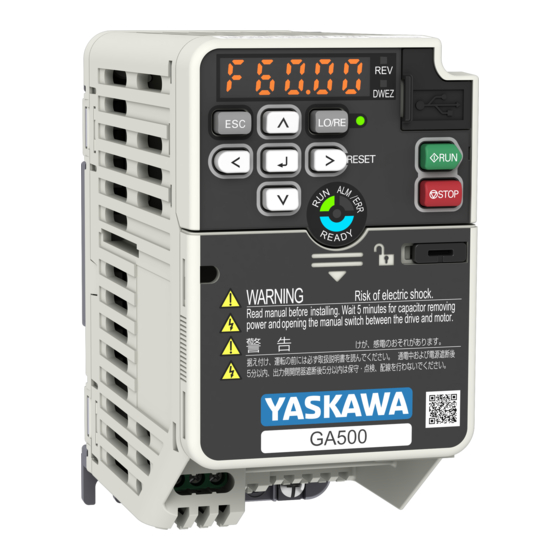
YASKAWA AC Drive GA500
Supplemental Technical Manual
Revised Contents and Applicable Drive Models
Description
Introduction
Model
GA500
Software version PRG: 01013 or
later <1>
All GA500 drives
EZZ023995<1>
December 2019
1 / 5
Advertisement

Subscribe to Our Youtube Channel
Related Manuals for YASKAWA GA500


Summary of Contents for YASKAWA GA500
- Page 1 Read this manual together with “ Installation & Primary Operation” (TOEP C710617 52) included with the product and the “ GA500 Technical Reference” (SIEP C710617 52) that you can download from our documentation website. Read and understand the safety information and precautions before you start to use the product.
- Page 2 2. Addition of Parameter Not Initialized when A1-03 = 2220, 3330 [Initialize Parameters = 2-Wire Initialization, 3-Wire Initialization] Even when you set A1-03 = 2220, 3330 [Initialize Parameters = 2-Wire Initialization, 3-Wire Initialization] to initialize the drive, A1-12 [Bluetooth ID] is not initialized. PRG: 01012 or earlier: The setting value of A1-12 is initialized.
- Page 3 Correct: Bold texts show additions and modifications. Wire Gauge Model L (mm) L1 (mm) φ d1 (mm) φ d2 (mm) (AWG) AI 0.25-6 YE 0.25 (24) 10.5 AI 0.25-6 BU 0.34 (22) AI 0.34-6 TQ 10.5 AI 0.5-6 WH 0.5 (20) 12.0 AI 0.5-6 OG AI 0.75-6 GY...
- Page 4 7. Correction of Interlock Circuit Example Wrong: p.92, SIEPC71061752B Figure 3.52 Interlock Circuit Example Correct: These are the modifications: Drive 1 Terminal C2 → Terminal C1 Diagram of Photocoupler 1 Figure 3.52 Interlock Circuit Example 4 / 5 EZZ023995<1>...
- Page 5 8. Corrections of the Status of Digital Input/Output Terminals during Auto-Tuning Wrong: p.137, SIEPC71061752B Table 4.16 Status of Input/Output Terminals during Auto-Tuning Correct: Underlined texts show modifications. Table 4.16 Status of Input/Output Terminals during Auto-Tuning 5 / 5 EZZ023995<1> December 2019...
- Page 6 Read this manual together with the manual (TOEP C710617 xx) included with the product and the GA500 Technical Manual (SIEP C710617 xx) that can be found on our documentation website. Always observe the safety messages and precautions to ensure correct application of the product.
- Page 7 C4-23[Current Control Gain] PRG: 01013 and Earlier PRG: 01014 or Later: [RUN] icon removed You cannot change the parameter setting during Run. 2. Addition of Speed Search Regeneration Determination Parameter Parameter for setting the regeneration determination level during speed search has been added. ■Added parameter Default Name...
- Page 8 This supplemental manual describes the functions added with a GA500 software upgrade (PRG: 01015), and should be read to ensure proper usage. Read this manual together with the GA500 Quick Start Guide (TOEP C710617 xx) included with the product and the GA500 Technical Manual (SIEP C710617 xx) that can be found on our documentation website.
- Page 9 OFF. The data log can now be recorded continuously while the GA500 is in operation on an external 24 V power supply. [Appendix] Operation of Drive and Options during Operation of the External 24 V Power Supply The following table summarizes operation of the drive and options when the main circuit power supply is OFF and external 24 V power supply is being provided to terminals PS-AC.
- Page 10 *1 Multi-function digital inputs operate as follows. Multi-function digital inputs If the main circuit power supply is turned OFF, the multi-function digital input terminal will not operate even if the external 24 V power supply is provided to terminals PS-AC. When N.O.
Need help?
Do you have a question about the GA500 and is the answer not in the manual?
Questions and answers
We have a Yaskawa GA 500 that we cant get to follow the peramiters It will always start out on an F125.0 we dont know if its a fault or what