Table of Contents
Advertisement
Quick Links
Advertisement
Table of Contents

Related Manuals for ICP DAS USA DNP-211-S


Summary of Contents for ICP DAS USA DNP-211-S
- Page 1 User Manual May 2024 v1.00 DNP-211-S DNP3 Slave to Modbus TCP Client Gateway...
- Page 2 Copyright © 2021 ICP DAS Co., Ltd. All rights are reserved. Trademarks Names are used for identification purposes only and may be registered trademarks of their respective companies. Document Revision Version Author Date Description 1.00 Ming 2024/05/06 First Released Revision Version 1.00 DNP-211-S User Manual 2024/05/28...
-
Page 3: Table Of Contents
Hardware ....................8 2.1. Dimensions ..................... 8 2.2. Appearance ..................... 9 2.3. LED Indicator ..................10 Getting Started With DNP-211-S ............11 3.1. Preparations for Devices ..............11 3.2. Hardware Wiring and setting rules ..........11 3.3. DNP-211-S Utility ................13 3.4. -
Page 4: Introduction
“Intranet” or “Internet” environment using the TCP/IP protocols. The most common use of the protocols at this time is for Ethernet attachment of PLC’s, I/O modules, and gateways to other simple field buses or I/O networks. Version 1.00 DNP-211-S User Manual 2024/05/28... -
Page 5: About Dnp-211-S
Its main function is to integrate existing Modbus slave devices into DNP3 slave devices for control by a DNP3 master station. In the DNP3 network, the DNP-211-S acts as a DNP3 slave device supporting several common data groups and variations to facilitate communication with the master station. -
Page 6: Specifications
Support RS-485 / Ethernet Group 1, 10, 11, 30, 40, 41 DNP3 DI: 8192 DO: 8192 Data Point AI: 2048 AO: 2048 Power Supply Voltage +12 to +48 VDC Consumption 4.8 W Connector 3-pin removable terminal block Version 1.00 DNP-211-S User Manual 2024/05/28... - Page 7 Mechanism Dimensions 35 mm x 167 mm x 119 mm Casing Metal Installation DIN-Rail Environment Operating Temp. -25°C ~ +75°C Storage Temp. -30°C ~ +85°C Humidity 10 ~ 90% RH, non-condensing Version 1.00 DNP-211-S User Manual 2024/05/28...
-
Page 8: Hardware
2. Hardware 2.1. Dimensions Version 1.00 DNP-211-S User Manual 2024/05/28... -
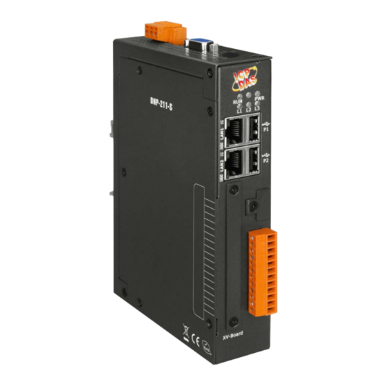
Page 9: Appearance
2.2. Appearance Version 1.00 DNP-211-S User Manual 2024/05/28... -
Page 10: Led Indicator
2.3. LED Indicator There are five LEDs to indicate the various states of the DNP-211-S. Since the power-on time of DNP-211-S is about 1 minute, if you need to observe the status of these LEDs, please wait 1 minute after powering on. -
Page 11: Getting Started With Dnp-211-S
3. Getting Started With DNP-211-S 3.1. Preparations for Devices In addition to the DNP-211-S, please prepare the following: 1. Power Supply: +12 ~ +48 VDC (Ex: DP-665) 2. Ethernet Hub or Switch (Ex: NS-205) 3. PC/NB: Can connect to the network and set the network 3.2. - Page 12 3. When both LAN1 and LAN2 are enabled, they must be connected to two separate networks. 4. Modbus TCP and DNP3 devices have no fixed LAN settings. Version 1.00 DNP-211-S User Manual 2024/05/28...
-
Page 13: Dnp-211-S Utility
DNP-211-S Utility is a utility for DNP-211-S to generate dedicated connection settings and I/O mapping table, and it can also be used to modify the IP address and to update the firmware of the DNP-211-S. After opening DNP_211_S_Utility, the screen will be as below: Version 1.00... - Page 14 DNP3 Mode: The methods of connecting with the DNP3 master station include TCP, UDP, and Serial: TCP: Set the IP and the Port to be used for the DNP-211-S module. UDP: Set the DNP-211-S's Local IP/Port and the master station's Remote IP/Port.
- Page 15 Local Outstation ID: Slave ID of the DNP-211-S (0 ~ 65519). Remote Master ID: DNP3 master ID (0 ~ 65519). 3. Set the total number of I/O points on the DNP-211-S and the number of Modbus slave devices to be controlled.
- Page 16 Analog Input Amount: Set Word AI channels for DNP-211-S. Int32 Input Amount: Set Int32 AI channels for DNP-211-S. Float Input Amount: Set Float AI channels for DNP-211-S. Double Input Amount: Set Double AI channels for DNP-211-S. Analog Output Amount: Set Word AO channels for DNP-211-S.
- Page 17 Polling Timer (ms): Cycle time of Modbus commands. Add button: Press the "Add" button to add the aboved setting to the configuration file. Insert button: Press "Insert" to insert the setting above the selected item. Version 1.00 DNP-211-S User Manual 2024/05/28...
- Page 18 7. Repeat steps 4 to 6 for all Modbus TCP slaves settings. 8. Click "Export" to output the DNP211S_Config.toml file. 9. Click "Upload," enter the DNP-211-S's IP, and press "Upload" to load the file. After loading, wait for the DNP-211-S to reboot automatically to complete the configuration.
- Page 19 "Set Lan" to open the Network Configuration screen. Enter the current IP address of the DNP-211-S for connection. Once connected successfully, the current IP settings for the two LAN ports of the DNP-211-S will be displayed. After modification, press "Set all" to change the IP settings.
- Page 20 3.3.5 Update the Firmware of the DNP-211-S Link to the firmware download web page for the DNP-211-S, download the latest firmware d2s_xxxx.tar.gz file, and use the "Upload" function of the DNP-211-S Utility to upload the firmware. Note: After updating the firmware, the DNP-211-S will automatically reboot.
-
Page 21: Dnp-211-S Tester
After opening the DNP-211-S Tester, the screen will appear as follows: 1. First, enter the DNP3 side IP address and IP port of the DNP-211-S for connection. 2. After successful connection, the following screen will appear. - Page 22 4. At this point, you can choose other actions, such as entering 5 to prepare Write AO. Follow the prompt to input “Output Address” 0 and “Output Data” 10. The execution screen will appear as follows.。 Version 1.00 DNP-211-S User Manual 2024/05/28...
Need help?
Do you have a question about the DNP-211-S and is the answer not in the manual?
Questions and answers