
Related Manuals for ICP DAS USA DNP-211


Summary of Contents for ICP DAS USA DNP-211
- Page 1 User Manual Version 1.0.1 Jun 2022 DNP-211 DNP3 Master to Modbus TCP Server Gateway...
- Page 2 Copyright © 2021 ICP DAS Co., Ltd. All rights are reserved. Trademarks Names are used for identification purposes only and may be registered trademarks of their respective companies. Document Revision Version Author Date Description 1.0.0 Ming 2021/10/06 First Released Revision Version 1.0.1 DNP-211 User Manual 2022/06/01...
-
Page 3: Table Of Contents
Specifications..................5 Hardware ....................7 2.1. Dimensions ..................... 7 2.2. Appearance ..................... 8 2.3. LED Indicator ................... 9 Getting Started With DNP-211 ............10 3.1. Preparations for Devices ..............10 3.2. Hardware Wiring .................. 10 3.3. DNP-211 Utility ..................10 3.3.1. -
Page 4: Introduction
“Intranet” or “Internet” environment using the TCP/IP protocols. The most common use of the protocols at this time is for Ethernet attachment of PLC’s, I/O modules, and gateways to other simple field buses or I/O networks. Version 1.0.1 DNP-211 User Manual 2022/06/01... -
Page 5: About Dnp-211
It supports several commonly used data groups and variables and can communicate with slave devices. From the perspective of Modbus TCP network, DNP-211 is a Modbus TCP server, which can receive commands from Modbus TCP client, and process these commands to reply or send related DNP3 data. - Page 6 3-pin Removable Terminal Block Mechanism Dimensions 35 mm x 167 mm x 119 mm Casing Metal Installation DIN-Rail Environment Operating Temp. -25°C ~ +75°C Storage Temp -30°C ~ +85°C Humidity 10 ~ 90% RH, non-condensing Version 1.0.1 DNP-211 User Manual 2022/06/01...
-
Page 7: Hardware
2. Hardware 2.1. Dimensions Version 1.0.1 DNP-211 User Manual 2022/06/01... -
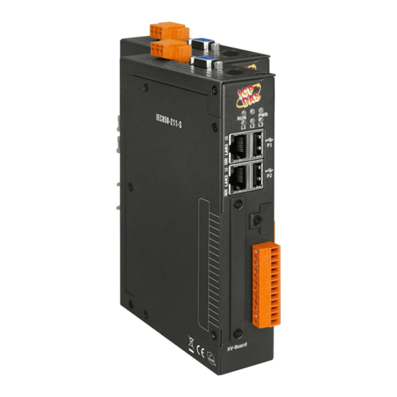
Page 8: Appearance
2.2. Appearance Version 1.0.1 DNP-211 User Manual 2022/06/01... -
Page 9: Led Indicator
2.3. LED Indicator There are five LEDs to indicate the various states of the DNP-211. The following is the illustration of these five LEDs. LED Name LED Status Description Power on Power failure OS is running Blink OS stops running... -
Page 10: Getting Started With Dnp-211
3.2. Hardware Wiring Connect the DNP-211 with the RJ-45 Ethernet port LAN1 to an Ethernet hub/switch and PC. You can also link directly the DNP-211 to PC with an Ethernet cable. After power is connected, please wait 1 minute for DNP-211 start-up procedure. -
Page 11: Dnp-211 Utility Introduction
DNP-211 Utility Introduction The DNP_211_Utility is as below: DNP-211 Communication Configure Gateway Type: Display gateway type of the DNP-211. Gateway IP: Modbus TCP IP address of the DNP-211 (LAN1 IP). Port: Modbus TCP port of the DNP-211 Version 1.0.1 DNP-211 User Manual... - Page 12 TCP mode: Remote IP, Remote Port: IP and port of target outstation. UDP mode: Remote IP, Remote Port: IP and port of target outstation. Source IP, Source Port: IP and port of the DNP-211. Serial mode: Version 1.0.1 DNP-211 User Manual...
- Page 13 Output mode: DO / AO output mode (only for write command) Description: User’s self-filled description Utility Button Import: Import the existing GatewayConfig.toml configuration file Export: Export the current settings to the GatewayConfig.toml Modbus Map: Generate the currently set Modbus address table Version 1.0.1 DNP-211 User Manual 2022/06/01...
- Page 14 Upload: Upload the GatewayConfig.toml configuration file or d2m_xxxxxxxx.tar.gz firmware file to DNP-211 Note: DNP-211 must be rebooted after upload configuration or firmware file. Version 1.0.1 DNP-211 User Manual 2022/06/01...
-
Page 15: Dnp-211 Reader
3.4.2. DNP-211 Reader Introduction DNP-211 Reader is a simple test utility for DNP-211 module. It can import the “toml” file produced by DNP-211 Utility and test the connection and I/O function. The dialog of DNP-211 Reader is as bellow: First clicked “Import”... - Page 16 After import the toml file, click “Connect” to connect with DNP-211 module. If successful, DNP-211 Reader will show as below. Disconnect: Disconnect with PC and DNP-211. Status: Connection status of all Outstations (Modbus 30001 ~ 30032). 0: The setting of the DNP-211 not includes the Outstation.
- Page 17 7 DO points, bit0 ~ bit6. Fill the “Start bit” and “Output Amount” bits and input the output value (hex) such as 7F. Finally click “Send” to send the command, the “7F”command will let DO bit0 ~ bit6 all ON. Version 1.0.1 DNP-211 User Manual 2022/06/01...
- Page 18 Outstation. AO Output: This mode can select AO channel to output. Fill in the decimal value to be output in the “Output Value” field, and finally press the “Send” button to output the command. Version 1.0.1 DNP-211 User Manual 2022/06/01...
- Page 19 Windows: Show input form of every Outstation. Version 1.0.1 DNP-211 User Manual 2022/06/01...
-
Page 20: Appendix A: Modbus Map
Appendix A: Modbus Map The Modbus Map function of DNP-211 Utility can export the mapping table of Modbus and DNP3 as below: Register field: Modbus address, 0xxxx: DO, 1xxxx: DI, 3xxxx: AI, 4xxxx: AO Slave field: DNP3 Outstation ID Group field: I/O type of the Outstation... -
Page 21: Appendix B: Mapping Rule
Appendix B: Mapping Rule Version 1.0.1 DNP-211 User Manual 2022/06/01...
Need help?
Do you have a question about the DNP-211 and is the answer not in the manual?
Questions and answers