Table of Contents
Advertisement
Quick Links
Magnetic Stirrer
MFD/MFH800 Series
Instruction Manual
Second Edition
Thank you for choosing MFD/MFH series Magnetic
Stirrer from Yamato Scientific Co., Ltd.
In order to use the product properly, please read this
"Instruction Manual" and "Warranty" carefully and
familiarize yourself with them before use. Always keep
equipment documentation safe and close at hand for
convenient future reference.
The warnings in the instruction manual are
important for the safe use of the product.
Please read carefully and familiarize
yourself with the product before use.
Yamato Scientific Co. ,Ltd.
Printed on recycled paper
Advertisement
Table of Contents
Troubleshooting

Subscribe to Our Youtube Channel
Related Manuals for Yamato MFD Series


Summary of Contents for Yamato MFD Series
- Page 1 Instruction Manual Second Edition Thank you for choosing MFD/MFH series Magnetic Stirrer from Yamato Scientific Co., Ltd. In order to use the product properly, please read this "Instruction Manual" and "Warranty" carefully and familiarize yourself with them before use. Always keep equipment documentation safe and close at hand for convenient future reference.
- Page 3 If you do not know the model number, refer to the model number on the model rating sticker on the side of the product. Type rating sticker affixed location MFD Series Power supply cable *Cord specifications and plug shape differ depending on the model.
-
Page 4: Table Of Contents
Residual Risk Map ........................5 List of residual risks (instructions for risk avoidance) ..............6 2. names and functions of each part ....................7 Product appearance (MFD series) ................... 7 Product appearance (MFH series) ................... 8 Operation panel ........................9 3. - Page 5 Precautions before Inspection ....................33 Precautions in Daily Maintenance ..................33 Maintenance and Inspection ....................33 8. EXTENDED STORAGE AND DISPOSAL ................. 34 Extended storage/disposal ..................... 34 Disposal Considerations ......................34 9. TROUBLESHOOTING ......................35 Reading Error Codes ......................35 9.
-
Page 6: Safety Precautions
1. SAFETY PRECAUTIONS Explanation of Symbols A Word Regarding Symbols Various symbols are provided throughout this text and on equipment to ensure safe operation. Failure to comprehend the operational hazards and risks associated with these symbols may lead to adverse results as explained below. -
Page 7: Symbol Glossary
1. SAFETY PRECAUTIONS Symbol Glossary WARNING / CAUTION Danger!: High Caution: Burn Caution: Shock General Temperature Hazard! Hazard! RESTRICTION General Do Not Do Not Touch Restriction Disassemble ACTION General Action Connect Ground Disconnect Power Inspect Level Installation Required Wire supply cable plug Regularly... -
Page 8: Warnings And Cautions
1. SAFETY PRECAUTIONS Warnings and Cautions WARNING Install in a location free of flammables and explosives. NEVER install or operate unit in a flammable or explosive gas atmosphere This unit is not explosion-proof and may cause explosion or ignition. See "LIST OF HAZARDOUS SUBSTANCES" (P. ) for information on flammable and explosive gases. - Page 9 1. SAFETY PRECAUTIONS Warnings and Cautions Be aware of the effects of magnetic fields. This product uses a strong magnetic force magnet. Please be careful when using data storage media or cardiac pacemakers, etc., as they may malfunction. Do not subject the top plate to strong shocks. If a strong impact is applied, the top plate may be deformed or the coating may peel off, making the container unstable or heating unstable.
-
Page 10: Residual Risk Map
1. SAFETY PRECAUTIONS Residual Risk Map These figures indicate positions of caution labels. The numbers shown in the figure indicate the numbers listed in the "List of Residual Risks" in this manual. For details of individual residual risks, see the List of Residual Risks. MFD800 Series Caution: Burn Hazard! Sticker 12... -
Page 11: List Of Residual Risks (Instructions For Risk Avoidance)
1. SAFETY PRECAUTIONS List of residual risks (instructions for risk avoidance) The following is a list of residual risks to prevent harm to the human body in the use of our products. Be sure to fully understand or receive instructions on how to use, maintain and inspect equipment before starting operation. -
Page 12: Names And Functions Of Each Part
2. names and functions of each part Product appearance (MFD series) Top plate Pole mounting screws and screw caps (Pole is optional) Adjuster Power switch Operation panel 【MFD800/MFD800-Y】 AC power connector Service outlet (max. 5A) Fuse for service outlet (5A) Fuse for internal circuit (0.5A) -
Page 13: Product Appearance (Mfh Series)
2. COMPONENT NAMES AND FUNCTIONS Product appearance (MFH series) Top plate Pole mounting screws and screw caps (Pole is optional) Adjuster Power switch Operation panel 【MFH800/MFH800-Y】 AC power connector External temperature sensor connector Service outlet (max. 5A) Fuse for service outlet (5A) Fuse for internal circuit (7A) *To replace the fuse (see p. -
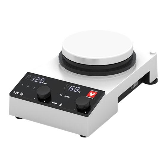
Page 14: Operation Panel
2. COMPONENT NAMES AND FUNCTIONS Operation panel 【MFD800】 ① ② ⑤ ③ ④ 【MFH800】 ① ⑥ ② ⑦ ⑧ ⑪ ⑤ ⑨ ③ ④ ⑩ Number Name Function ① Motor rotation speed While the display is lit, the current speed of the agitation motor is shown. While blinking, display the set Motor rotation speed is displayed. -
Page 15: Pre-Operation Procedures
3. PRE-OPERATION PROCEDURES Precautions for installation Choose an appropriate installation site. DO NOT install unit: ・ where installation surface is not completely level, not even or not clean. ・ where flammable or corrosive gases/fumes may be present. ・ where external temperature will exceed 41°C, will fall below 3°C or will fluctuate largely. ・... - Page 16 3. PRE-OPERATION PROCEDURES Precautions for installation Always connect power cable to appropriate facility outlet or terminal. Connect power cable to a suitable facility outlet or terminal, according to the electrical requirements. Electrical MFH800 AC 100 V single-phase 50/60 Hz 11 A (breaker capacity; 15 A) requirements: MFD800 AC 100 V single-phase 50/60 Hz 6 A (breaker capacity;...
- Page 17 3. PRE-OPERATION PROCEDURES Installation Precautions Initial operation When using the product for the first time, an unusual odor may occur if the product is heated to a high temperature. This is due to the decomposition of the binding material in the heat insulator and is not a product failure.
-
Page 18: Pre-Operative Preparations
4.PRE-OPERATIVE PREPARATIONS Various Functions The various functions of the product are as follows. The following features are available only in MFH800 and not in MFD800. Name Description Page This function is intended to prevent abnormal overheating of the product. Overheat prevention P.26 If the temperature of the top plate rises above 400 °C, the control stops. -
Page 19: Adjuster Adjustment
4.PRE-OPERATIVE PREPARATIONS Adjuster adjustment Adjust the adjusters on the two rear legs so that the main body is level. Adjuster <Procedure> When the adjuster is turned clockwise when the main unit is viewed from above, the adjuster will extend. Adjuster extends... -
Page 20: Protective Cover Installation
4.PRE-OPERATIVE PREPARATIONS Protective cover installation A protective cover is provided to reduce corrosion of the main unit due to chemicals, etc. (Included, optional) <Procedure> ① Pull the control knob upward to remove it. Control knob ② Remove the two screw caps on the back of the main unit Screw cap ③... -
Page 21: Attachment Of Heat Cutter
4.PRE-OPERATIVE PREPARATIONS Attachment of heat cutter Heat cutter plate Heating without using the heat cutter plate will cause the internal temperature of the main unit to rise, which may result in a malfunction. Installation of external temperature sensor 【MFH800 series】 <Procedure>... -
Page 22: Pole (Optional) Installation
4.PRE-OPERATIVE PREPARATIONS Pole (optional) installation <Procedure> Screw cap ① Remove the screw caps from the mounting screws on the main unit. ② Tighten the nuts and washers on the pole in this order to the mounting screws on the body. Pole Washer ③... -
Page 23: Offset Bar (Optional) Installation
4.PRE-OPERATIVE PREPARATIONS Offset bar (optional) installation When using a large container such as an oil bath on the stirring table, an offset bar can be used without interfering with the pole. <Procedure> ① Install the nuts and washers on the pole in this order Pole and tighten them onto the offset bar screws. -
Page 24: How To Use The Container Fall Prevention Frame (Optional)
4.PRE-OPERATIVE PREPARATIONS How to use the container fall prevention frame (optional) When using a vessel on the top plate, the risk of the vessel tipping over or falling can be reduced by using a frame to prevent the vessel from tipping over. <Procedure>... -
Page 25: How To Use Aluminum Blocks (Optional)
4.PRE-OPERATIVE PREPARATIONS How to use aluminum blocks (optional) DO NOT touch hot surfaces Do not touch the aluminum block and surrounding parts during or after operation. Burn injury may result. By placing an aluminum block on the top plate, heating can be mediated by the aluminum block. <Procedure>... -
Page 26: How To Use The Aluminum Block Handle (Optional)
4.PRE-OPERATIVE PREPARATIONS How to use the aluminum block handle (optional) The aluminum block handle allows easy carrying of the aluminum block on the top table. <Procedure> ① Insert the end of the handle into the handle insertion hole in each aluminum block. All aluminum blocks have insertion holes. -
Page 27: How To Use The Double-Handled Aluminum Block Handle (Optional)
4.PRE-OPERATIVE PREPARATIONS How to use the double-handled aluminum block handle (optional) When using 1000mL or 2000mL size aluminum blocks, they can be easily carried by using the double-handled aluminum block handles. <Procedure> Handle Insertion Hole ① Insert the end of the handle into the handle insertion hole in each aluminum block. -
Page 28: Operation Procedures
5. OPERATION PROCEDURES Operation method: Stirring function (operated on the left side of the operation panel) This section explains how to operate the stirring function on the left side of the operation panel. It operates completely independent of the previous stirring function. Be careful not to press the wrong switch. -
Page 29: About Rotation Mode
5. OPERATION PROCEDURES About Rotation Mode The rotation mode allows the rotation speed of the agitation motor to be varied repeatedly. The rotation modes are as follows. № Name Description (RPM) Fixed speed operation mode Set number of Slowdown rotations setting Slowup Continuous operation at set motor... -
Page 30: Operation Method: Temperature Control Function (Operated On The Right Side Of The Panel, Only Available On Mfh800 Series)
5. OPERATION PROCEDURES Operation method: Temperature control function (operated on the right side of the panel, only available on MFH800 series) This section explains how to operate the temperature control function on the right side of the operation panel, which is available only for the MFH800 series. It operates completely independent of the previous stirring function. -
Page 31: Temperature Control By External Temperature Sensor (Only Available For Mfh800 Series)
5. OPERATION PROCEDURES Temperature control by external temperature sensor (only available for MFH800 series) Temperature control operation is possible with the attached external temperature sensor. We will explain how to set this up. The operation method is the same as the previous temperature control using an internal sensor. 1. -
Page 32: User Setting (Only Available For Mfh800 Series)
5. OPERATION PROCEDURES User setting (only available for MFH800 series) The following features can be configured in the user settings. Settings are made in the user settings menu, and both agitation and temperature control can be entered into the menu while operation is stopped. -
Page 33: Temperature High Limit Function
5. OPERATION PROCEDURES Temperature high limit function If the top plate temperature exceeds the set temperature, all controls are stopped and an error(E32) is displayed. This section describes how to operate the system. 1. Enter the user settings menu ・ Confirm that both agitation and temperature control are stopped. -
Page 34: Calibration Offset
5. OPERATION PROCEDURES Calibration offset If there is a difference between the actual temperature and the controller's displayed temperature, this function compensates (offsets) this difference. It is possible to make a uniform correction to the positive or negative side for all temperature zones. Set value: -5.0 to +5.0 (factory default: "0.0") ●... -
Page 35: User Setting: Power Failure Recovery Mode Selection (Only Available For Mfh800 Series)
5. OPERATION PROCEDURES User setting: Power failure recovery mode selection (only available for MFH800 series) Select recovery mode for the event of a power failure. Setting OFF: Operation is stopped when power is restored. Setting ON : When power failure is restored, operation continues in the state immediately before power failure. -
Page 36: User Setting: Led Brightness Switching Function (Only Available For Mfh800 Series)
5. OPERATION PROCEDURES User setting: LED brightness switching function (only available for MFH800 series) Sets the LED brightness of the operation panel. The brightness can be changed in 9 steps from "0 to 8". (Default setting: "4") Changes the brightness of the operation panel. This section describes how to operate the system. 1. -
Page 37: Handling Precautions
6. HANDLING PRECAUTIONS Warnings and Cautions CAUTION NEVER process explosive or flammable substances Never attempt to process explosives, flammables or any items which contain explosives or flammables. Fire or Explosion may result. See " 13. LIST OF HAZARDOUS SUBSTANCES" (P.41) Resin container advisory. -
Page 38: Inspection And Maintenance
7. INSPECTION AND MAINTENANCE Precautions before Inspection Warning Be sure to disconnect power supply cable before daily inspection and maintenance. ⚫ ⚫ Perform inspections and maintenance when unit is at room temperature. ⚫ Never attempt to disassemble unit. Precautions in Daily Maintenance CAUTION Clean unit using soft damp cloth. -
Page 39: Extended Storage And Disposal
Dispose of this unit in accordance with local laws and regulations. Dispose of or recycle this unit in a responsible and environmentally friendly manner. Yamato Scientific Co., Ltd. strongly recommends disassembling unit, as far as is possible, in order to separate parts and recycle them in contribution to preserving the global environment. The main components and materials used in this product are as follows. -
Page 40: Troubleshooting
9. TROUBLESHOOTING Reading Error Codes The product is equipped with a self-diagnostic function. The table shows the error code, cause, and treatment method when an abnormality occurs. [Error Codes] If an error occurs in the product, the following error code is displayed in the rotation or temperature display (right side 7 segments) on the display panel, and operation stops in the state shown in the table corresponding to the error code. -
Page 41: Troubleshooting
⚫ If problem persists, call for service. 9. TROUBLESHOOTING Reading Error Codes Other warning signs Warning Sign Warning Name Possible causes and solutions High Temperature ⚫ The warning is displayed when the temperature of the Warning top plate exceeds 50°C while the temperature control (Displayed on temperature (HOT indication) is stopped. -
Page 42: Service & Repair
Warranty card will be handed by dealer or Yamato personnel upon delivery and installation. or will be attached to equipment if no one from dealer or Yamato is to be present at delivery and installation. Register warranty card at https://www.yamato-net.co.jp/support/warranty.htm https://www.yamato-net.co.jp/support/warranty.htm... -
Page 43: Specifications
11. SPECIFICATIONS Specifications (MFD) form (something takes) MFD800 MFD800-Y MFD810-B MFD810-Y Product name Magnetic Stirrer Motor rotation speed range 50 to 1600 rpm (set in 10 rpm increments) Motor DC brushless motor (31 W) Magnets Neodymium magnet Error message White LED digital display Exterior parts Aluminum Die Casting Top plate... -
Page 44: Specifications (Mfh)
11. SPECIFICATIONS Specifications (MFH) form (something takes) MFH800 MFH800-Y MFH810-B MFH810-Y Product name Magnetic Stirrer with Hot Plate Motor rotation speed range 50 to 1600 rpm (set in 10 rpm increments) Temperature control range (Room temperature + approx.25*2) °C to 310°C ±1.5 °C at 100 °C (internal temperature sensor) Temperature control accuracy*1 ±1.0 °C at 50 °C (external temperature sensor) -
Page 45: Reference Data
12. Reference Data Temperature rise characteristics Room temperature: 23°C, no load on the top plate Temperature rise characteristics (internal sensor) Setting 300 °C Setting 250 °C Setting 200 °C Setting 150 °C Setting 100 °C Setting 50 °C Time (seconds) -
Page 46: List Of Hazardous Substances
13. LIST OF HAZARDOUS SUBSTANCES Never attempt to process explosives, flammables or any items which contain explosives or flammables. Table 13.1 List of hazardous substances ① Nitroglycol, nitroglycerin, nitrocelluloses and other explosive nitrate esters ② Trinitrobenzen, Trinitrotoluene, Picric Acid and other explosive nitro compounds ③... -
Page 47: Standard Installation Manual
STANDARD INSTALLATION MANUAL Please install the equipment in accordance with the following items. (Please confirm separately in the case of optional or special specifications.) Installation Installation proved by Installation Model Serial Number Judgment Date (Company name) proved by Chapter No. & Reference page of №... -
Page 48: List Of Options
15. List of Options A variety of options are available to suit your application. Please contact your distributor or " 16. Contact information(p.48)" to purchase the product. Product name Model/Product Description Product Contents Code Protective cover (for MFD) OA154/281395 Protective cover to protect Silicon protective cover ×1 the MFD main unit from dirt and sample scattering. - Page 49 15. List of Options Product name Model/Product Description Product Contents Code Power supply cable (round OA183/281587 Power cable with round Power supply cable (round terminal 2m) terminals. terminal 2m)×1 Aluminum block handle OA144/281382 Handles for carrying Aluminum block handle×1 various types of aluminum blocks.
- Page 50 15. List of Options Product name Model/Product Description Product Contents Code Muff OLM44/231632 Muff×1 Forφ5~φ13 OLM46/231633 Muff×1 Forφ6~φ17 OLM48/231634 Muff×1 Forφ9.5~φ29 Double Opening Clamp OLM50/231635 Tightness adjustment Clamp×1 range:3~55mm Shaft diameter:10mm compatible flask:50mL~ 3000mL OLM52/231636 Tightness adjustment Clamp×1 range:3~80mm Shaft diameter:12mm compatible flask:50mL~5000mL Product name...
- Page 51 15. List of Options List of Aluminum Blocks by Container Used Integrated model Shape target flask Model/Product Identification Code number Eggplant flask 200ml OA167/281432 200JE (sold separately) 300ml OA171/281436 300JE 500ml OA172/281566 500JE 1000ml OA173/281567 1000JE 2000ml OA174/281568 2000JE Round flask 200ml OA175/281572 200JR...
- Page 52 15. List of Options Holder Name Body shape Model/Product Code OA156/281421 Single Holder Triple Holder OA157/281422 For small containers Model/Product Identification Description Shape target flask Code number Eggplant flask 10ml OA169/281434 10JE (sold separately) 20ml OA168/281433 20JE 30ml OA165/281430 30JE ISO Round 25ml available...
-
Page 53: Contact Information
フリーコール 0120-405-525 携帯電話からのお問い合わせは:0570-064-525 FAX:055-284-5210 受付時間:9:00~17:30 ※土・日・祝日・振替休日を除く(12:00~13:00 の間も受け付けております) http://www.yamato-net.co.jp 2)USA・Canada・Latin America Yamato Scientific America Inc. 925 Walsh Avenue, Santa Clara,CA 95050, U.S.A http://www.yamato-usa.com Toll Free: 1-800-2-YAMATO (1-800-292-6286) 3)Other Country For repair service, maintenance service and consumables purchase support, please contact to our distributors from whom you purchased. - Page 54 Doing so may result in equipment malfunction, serious personal injury or death. Notice ● Instruction manual descriptions and specifications are subject to change without notice. ● Yamato Scientific Co., Ltd. will replace flawed instruction manuals (pages missing, pages out of order, etc.) upon request. Instruction Manual...
Need help?
Do you have a question about the MFD Series and is the answer not in the manual?
Questions and answers