Table of Contents
Advertisement
Quick Links
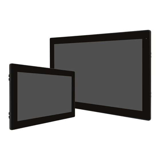
AUHMI-9XXC Series
10.1", 15.6", and 21.5" Intel Tiger Lake
Fanless Industrial Compact Size Panel PC
User Manual
Release Date
Revision
July.2023
V1.1
®2023 Aplex Technology, Inc.
All Rights Reserved.
Published in Taiwan
Aplex Technology, Inc.
15F-1, No.186, Jian Yi Road, Zhonghe District, New Taipei City 235, Taiwan
Tel: 886-2-82262881 Fax: 886-2-82262883
Email:
aplex@aplex.com
URL:
http://www.aplex.com
Advertisement
Table of Contents

Related Manuals for Aplex AUHMI-9 C Series


Summary of Contents for Aplex AUHMI-9 C Series
- Page 1 Fanless Industrial Compact Size Panel PC User Manual Release Date Revision July.2023 V1.1 ®2023 Aplex Technology, Inc. All Rights Reserved. Published in Taiwan Aplex Technology, Inc. 15F-1, No.186, Jian Yi Road, Zhonghe District, New Taipei City 235, Taiwan Tel: 886-2-82262881 Fax: 886-2-82262883 Email: aplex@aplex.com...
- Page 2 Revision History Reversion Date Description 2023/05/17 Initiation 2023/07/03 HELIO whole products rename to AUHMI AUHMI-9XXC Series User Manual...
-
Page 3: Warning
Disclaimer This information in this document is subject to change without notice. In no event shall Aplex Technology Inc. be liable for damages of any kind, whether incidental or consequential, arising from either the use or misuse of information in this document or in any related materials. -
Page 4: Safety Precautions
Safety Precautions Follow the messages below to prevent your systems from damage: ◆ Avoid your system from static electricity on all occasions. ◆ Prevent electric shock. Don‘t touch any components of this card when the card is power-on. Always disconnect power when the system is not in use. ◆... -
Page 5: Table Of Contents
Table of Contents Warning!_______________________________________ ..............2 Safety Precautions ..........................3 Chapter 1 System Product ......................6 Features ..........................6 Specifications .......................... 6 COM port definition ......................... 8 Standard LCD ........................... 9 High Brightness LCD ......................... 9 Power Consumption and PoE Application ................. 10 Dimensions ........................... - Page 6 4.8 Intel® HID Event Filter ........................74 List of Figures AUHMI-910C ............................11 IGURE IMENSIONS OF AUHMI-916C ............................11 IGURE IMENSIONS OF AUHMI-921C ............................12 IGURE IMENSIONS OF AUHMI-910CP(H) ..........................13 IGURE RONT IEW OF AUHMI-910CP(H) ..........................13 IGURE IEW OF AUHMI-916CP(H) ..........................
-
Page 7: Chapter 1 System Product
Chapter 1 System Product 1.1 Features ⚫ 10.1”, 15.6” and 21.5” Intel® 11 Fanless HMI Panel PC ⚫ Gap-free sealing and slim Front Frame Architecture and front panel ⚫ DC 9~36V wide-ranging power input ⚫ IP66 compliant front panel ⚫ Support High brightness LCD (option) 1.2 Specifications AUHMI-9XXC... - Page 8 8. 2 x COM (RS-422/485, isolated) (TB-528C2I) 9. 1 x LAN + 2 x USB 2.0 type A (TB-528E1U2) ◆ Backup Battery Pack (exclusive for high brightness model and no TB-528 series at the same time) ◆ 1 x 2W Speaker(exclusive 528 series and backup battery) ◆...
-
Page 9: Com Port Definition
Windows 11 Linux Ubuntu 20.04 above Environmental Operating 0~50°C/-20℃ to 60℃ (optional for 10.1”, 15.6”) Temperature Storage Temperature -30~70°C Humidity 10 to 95% @ 40°C, non-condensing Certification CE / FCC Class A, RoHS/REACH Compliant *Please make sure the input voltage measured from the “power input connector” is more than 9 volt; to keep the product work properly. -
Page 10: Standard Lcd
1.4 Standard LCD AUHMI-910CP AUHMI-916CP AUHMI-921CP Display Type 10.1” 15.6” 21.5” LED Backlight LED Backlight LED Backlight Max. Resolution 1280 x 800 1366 x 768 1920 x 1080 1920 x 1080 Max. Color 16.7M 16.7M 16.7M Luminance(cd/m²) 400-HD 500-FHD Contrast Ratio 800:1 500:1-HD 1000:1... -
Page 11: Power Consumption And Poe Application
* y* does not apply in Linux OS. * We suggest to use the adapter that Aplex approved. If you would like to adopt your own power supply or adapter, please add another 20-30% from the above power consumption to make sure the system can work correctly. -
Page 12: Dimensions
1.7 Dimensions Figure 1 Dimensions of AUHMI-910C Figure 2 Dimensions of AUHMI-916C AUHMI-9XXC Series User Manual... -
Page 13: Brief Description Of Auhmi-9Xxc Series
Figure 3 Dimensions of AUHMI-921C 1.8 Brief Description of AUHMI-9XXC Series There are 10.1” ~ 21.5” Industrial Compact Size Panel PC in AUHMI-9XXC series, which comes with flat front panel touch screen and fanless design. It is powered by Intel 11 Generation Core i3/i5 CPU Processors with two SO-DIMM DDR4 slot, up to 64GB 3200 MHz. -
Page 14: Figure 4 Front View Of Auhmi-910Cp(H)
Figure 4 Front View of AUHMI-910CP(H) Figure 5 Rear View of AUHMI-910CP(H) AUHMI-9XXC Series User Manual... -
Page 15: Figure 6 Front View Of Auhmi-916Cp(H)
Figure 6 Front View of AUHMI-916CP(H) Figure 7 Rear View of AUHMI-916C(H) AUHMI-9XXC Series User Manual... -
Page 16: Figure 8 Front View Of Auhmi-921Cp(H)
Figure 8 Front View of AUHMI-921CP(H) Figure 9 Rear View of AUHMI-921CP(H) AUHMI-9XXC Series User Manual... -
Page 17: Vesa Mounting
1.9 VESA Mounting 1.9.1. 10.1” The AUHMI-910C is designed to be VESA mounted as shown in Picture. Just carefully place the unit through the hole and tighten the given 4 x M4x8 screws from the rear to secure the mounting. Figure 10 AUHMI-910C VESA Mounting 1.9.2. -
Page 18: Panel Mounting
1.10 Panel Mounting 1.10.1. 10.1” Step1: Embed the main AUHMI-910C machine into the panel frame. Step2: Insert the latch into the specific hole on AUHMI-910C. Step3: Fix the latch with screw. Figure 12 AUHMI-910C Panel Mounting 1.10.2. 15.6” and 21.5” Step1: Embed the main AUHMI-916C/921C machine into the panel frame. -
Page 19: Auhmi-916C/Auhmi-921C Panel Mounting
Step2: Insert the latch into the specific hole on AUHMI-916C/921C.(The mounting kits are different from AUHMI-910C) Step3: Fix the latch with screw. Figure 13 AUHMI-916C/AUHMI-921C Panel Mounting AUHMI-9XXC Series User Manual... -
Page 20: Cable Cover
1.11 Cable Cover Due to natural mechanical limits, cable cover only fits 15.6” and 21.5” model. Turn the two small brackets into two sides to separate from 15.6” and 21.5” printing. Step 0: Please take care the L sharp bracket must install in accordance with the product mode. If you would like to install the cable cover into 15.6”, the mark “916”... -
Page 21: Auhmi-916C/Auhmi-921C Cable Cover Installation
Figure 14 AUHMI-916C/AUHMI-921C Cable Cover Installation AUHMI-9XXC Series User Manual... -
Page 22: Battery Kit Installation
1.12 Battery Kit Installation Step1: Insert the battery kit to the MB box kit and screw it with 4pcs M3x6 screws. Step2: Connect the battery cable to the MB connector. AUHMI-9XXC Series User Manual... -
Page 23: Mb Box Kit Attaches To The Front Kit
1.13 MB Box kit attaches to the Front Kit This part fits for all 10.1”, 15.6” and 21.5” models. Step1: Insert the MB Box Kit to the Front Kit. Step2: Use 2x M3x6 Pan-head screw to fix MB Box kit with Front kit at both left side and right side. Figure 15 AUHMI-910C MB Box kit attaches to Front Kit Figure 16 AUHMI-916C/921C MB Box kit attaches to Front Kit AUHMI-9XXC Series User Manual... -
Page 24: Warning For Separating Auhmi Box Pc
1.14 Warning for separating AUHMI BOX PC Step1: Recognize BOX PC is the blue one shown as picture above. Step2: Separate the BOX PC from Front Kit slightly. Step3: Separate successfully. Note: It may cause the M.2 space copper pillar damage if separate roughly. Figure 17 AUHMI-9C BOX PC separation warnings 1.15 Warning of HDMI/DP port insert Important:... -
Page 25: Chapter 2 Hardware
Chapter 2 Hardware SBC-7125 is an industrial motherboard developed on the basis of Intel Core I Processors, which provides abundant peripheral interfaces to meet the needs of different customers. Also, it features dual RJ45 connectors, 6-COM ports and one M.2 M-Key configuration, one DP/HDMI combo connector, one LVDS interface. - Page 26 Without re-driver IC 1 x USB 2.0 via 180°Pitch 2.0mm 2x5Pin DIP type header 2 USB2.0 signal 1 x SATA 3.0 connector: Data transfer rate up to 6Gb/s 1 x SATA power connector :90° pitch 2.0mm 2x5 pin male header 1 x DB9 Male Connector ◼...
- Page 27 1 x Nano SIM slot via onboard micro SD+ Nano SIM combo slot for mini-PCIe Buzzer 1 x Onboard buzzer Button 1 x Power Button via pitch 2.5mm 2pin terminal block and 180° pitch 2.0mm 2pin wafer 1 x Reset Button via 180° pitch 2.0mm 2pin wafer Power 1 x Power connector Management...
-
Page 28: Board Overview
2.2 Board Overview 2.2.1 Board Top View (units :mm) Buzzer DC IN Header ESPI Header Reset Button Battery Header Power Button SATA0 DP/HDMI SATA Power ▲USB2_3/4 TB-528 2x30 Pin Header ▼USB3_3/4 Clear CMOS ▲USB2_1/2 ▼USB3_1/2 RTC Battery LAN1 & LAN2 COM Port Audio AUHMI-9XXC Series User Manual... - Page 29 2.2.2 Board Bottom View USB Header SIM Card Slot EC Debug DIO Power Select (CN1_DIO) Audio Header AUHMI-9XXC Series User Manual...
-
Page 30: Jumpers Setting And Connectors
2.3 Jumpers Setting and Connectors 2.3.1 Pin Assignment: AUHMI-9XXC Series User Manual... - Page 31 AUHMI-9XXC Series User Manual...
- Page 32 AUHMI-9XXC Series User Manual...
- Page 33 AUHMI-9XXC Series User Manual...
- Page 34 AUHMI-9XXC Series User Manual...
- Page 35 2.3.2 Expansion Slot: a) M.2 Module installation Before installing the M.2 module into the M.2 socket, please make sure that the following safety cautions are well-attended. Make sure the PC and all other peripheral devices connected to it has been powered down.
- Page 36 Step 3: Screw tight the card onto the stand-off with a screw driver and a stand-off screw until the gap between the card and the stand-off closes up. The card should be lying parallel to the board when it’s correctly mounted. b) M-PCIe Module installation Before installing the Mini PCIe module into the Mini PCIe socket, please make sure that the fol- lowing safety cautions are well-attended.
- Page 37 Step 2: Press the end of the card far from the socket down until against the stand-off. Step 3: Screw tight the card onto the stand- off with a screw driver and a stand- off screw until the gap between the card and the stand-off closes up. The card should be lying paral- lel to the board when it’s correctly mounted AUHMI-9XXC Series User Manual...
-
Page 38: Chapter 3 Bios Setup Description
Chapter 3 BIOS Setup Description 3.1 Overview The BIOS is a program that takes care of the basic level of communication between the CPU and peripherals. It contains codes for various advanced features found in this system board. The BIOS allows you to configure the system and save the configuration in a battery-backed CMOS so that the data retains even when the power is off. - Page 39 <Enter> Enter the highlighted submenu + (plus key)/F6 Scroll forward through the values or options of the highlighted field - (minus key)/F5 Scroll backward through the values or options of the highlighted field <F1> Display general help <F2> Display previous values <F7>...
-
Page 40: Main Settings
3.2 Main Settings AUHMI-9XXC Series User Manual... -
Page 41: Advanced Settings
Advanced Settings AUHMI-9XXC Series User Manual... - Page 42 AUHMI-9XXC Series User Manual...
- Page 43 AUHMI-9XXC Series User Manual...
- Page 44 AUHMI-9XXC Series User Manual...
- Page 45 AUHMI-9XXC Series User Manual...
- Page 46 AUHMI-9XXC Series User Manual...
- Page 47 AUHMI-9XXC Series User Manual...
- Page 48 AUHMI-9XXC Series User Manual...
- Page 49 AUHMI-9XXC Series User Manual...
- Page 50 AUHMI-9XXC Series User Manual...
-
Page 51: Chipset Settings
3.4 Chipset Settings AUHMI-9XXC Series User Manual... - Page 52 AUHMI-9XXC Series User Manual...
- Page 53 AUHMI-9XXC Series User Manual...
- Page 54 AUHMI-9XXC Series User Manual...
- Page 55 AUHMI-9XXC Series User Manual...
-
Page 56: Security Settings
3.5 Security Settings AUHMI-9XXC Series User Manual... - Page 57 AUHMI-9XXC Series User Manual...
-
Page 58: Boot Settings
3.6 Boot Settings AUHMI-9XXC Series User Manual... -
Page 59: Save & Exit Settings
3.7 Save & Exit Settings AUHMI-9XXC Series User Manual... - Page 60 AUHMI-9XXC Series User Manual...
-
Page 61: Chapter 4 Installation Of Drivers
Chapter 4 Installation of Drivers This chapter describes the installation procedures for software and drivers under the windows 10. The software and drivers are included with the motherboard. The contents include Intel Chipset, Graphics chipset driver, Audio driver, Intel LAN Driver, Intel® Serial I/O, Intel® Management and Security Status Installer, Intel®... -
Page 62: Intel Chipset
4.1 Intel Chipset To install the Intel chipset driver, please follow the steps below. Step 1. Here is welcome page. Please make sure you save and exit all programs before install. Click Next. Step 2. Read the license agreement. Click Accept to accept all of the terms of the license agreement. - Page 63 Step 3. Click Install to begin the installation. Step 4. Click Finish to finish installation. AUHMI-9XXC Series User Manual...
-
Page 64: Intel® Hd Graphics Chipset
4.2 Intel® HD Graphics Chipset To install the Intel® HD Graphics Chipset, please follow the steps below. Step 1. Click Begin installation. Step 2. Read the license agreement. Click I agree to accept all of the terms of the license agreement. - Page 65 Step 3. Click Start to setup program. Step 4. Click Finish to complete installation. AUHMI-9XXC Series User Manual...
-
Page 66: Realtek Hd Audio Driver Installation
4.3 Realtek HD Audio Driver Installation To install the Realtek HD Audio Driver, please follow the steps below. Step 1. Click Next to continue. Step 2. Click Yes, I want to restart my computer now to complete the installation. AUHMI-9XXC Series User Manual... -
Page 67: Intel Lan Driver
4.4 Intel LAN Driver To install the LAN driver, please follow the steps below. Step 1. Click Install to start installation. Step 2. Click OK to confirm the installation procedure. AUHMI-9XXC Series User Manual... - Page 68 Step 3. Click Close to finish installation. Step 4. Choose Yes, restart the computer now to complete the installation. AUHMI-9XXC Series User Manual...
-
Page 69: Intel® Serial I/O
4.5 Intel® Serial I/O To install Intel® Serial I/O, please follow the steps below. Step 1. Click Next to continue. Step 2. Choose I accept the terms in the License Agreement and click Next to begin the installation. AUHMI-9XXC Series User Manual... - Page 70 Step 3. Click Next to continue. Step 4. Click Next to continue. AUHMI-9XXC Series User Manual...
- Page 71 Step 5. Click Finish to complete installation. AUHMI-9XXC Series User Manual...
-
Page 72: Intel® Management And Security Status Installer
4.6 Intel® Management and Security Status Installer Step 1. Click Install to continue the installation. Step 2. Click Finish to exit setup. AUHMI-9XXC Series User Manual... -
Page 73: Intel® Management Engine Components
4.7 Intel® Management Engine Components Step 1. Click Next to continue. Step 2. Choose I accept the terms in the License Agreement and click Next to continue. AUHMI-9XXC Series User Manual... - Page 74 Step 3. Click Next to continue. Step 5. Click Finish to complete installation. AUHMI-9XXC Series User Manual...
-
Page 75: Intel® Hid Event Filter
4.8 Intel® HID Event Filter Step 1. Click Next to continue. Step 2. Read the License Agreement and Click Yes to continue. AUHMI-9XXC Series User Manual... - Page 76 Step 3. Click Next to continue. Step 4. Choose Yes, I want to restart this computer now and click Finish to finish installation. AUHMI-9XXC Series User Manual...
Need help?
Do you have a question about the AUHMI-9 C Series and is the answer not in the manual?
Questions and answers