Swegon ESENSA PX Flex Installation Instructions Manual
Hide thumbs
Also See for ESENSA PX Flex:
- Operation & maintenance instructions manual (20 pages) ,
- Installation instructions manual (42 pages)

Related Manuals for Swegon ESENSA PX Flex


Summary of Contents for Swegon ESENSA PX Flex
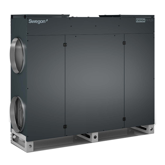
- Page 1 Installation instructions for the product range ESENSA PX Flex Consult the latest version of this manual on our website: www.swegon.com...
-
Page 2: Table Of Contents
GB.ESENSA PX Flex.MI.240327 Table of content Symbols and abbreviations ..........3 1. General .............4 1.1 General information ..........4 1.2 Installation applications ..........4 1.3 Transport within the site .........4 1.4 Remove the unit from the support ......4 1.5 Lifting ..............5 2. Product overview .........6 2.1 General information ..........6... -
Page 3: Symbols And Abbreviations
GB.ESENSA PX Flex.MI.240327 Symbols and abbreviations PLEATED FILTER PLATE HEAT EXCHANGER BACKWARD CURVED FAN Must be connected by a qualified electrician. WARNING ! Warning! Hazardous voltage. OUTDOOR AIR (1) EXHAUST AIR (3) EXTRACT AIR (2) SUPPLY AIR (4) www.swegon.com We reserve the right to alter specifications. -
Page 4: General
All staff must consult the instructions before starting any work The units ESENSA PX Flex 05, 10 and 13 are attached to the on the unit. Any damages to the unit (or parts of it) due to a pallet at the feet by metal parts. -
Page 5: Lifting
GB.ESENSA PX Flex.MI.240327 1.5 Lifting The ESENSA PX Flex 05, 10 and 13 units are equipped with The ESENSA PX Flex 20 unit is packaged differently. perforated feet for easy handling. The unit is surrounded by transport boards (see previous chap-... -
Page 6: Product Overview
GB.ESENSA PX Flex.MI.240327 2. Product overview 2.1 General information Horizontal left version (HL) Horizontal right version (HR) Vertical right version (VR) Vertical left version (VL) 1. Outdoor air 2. Extract air 3. Exhaust air 4. Supply air 2.2 Maintenance area... - Page 7 GB.ESENSA PX Flex.MI.240327 www.swegon.com We reserve the right to alter specifications.
-
Page 8: Components
GB.ESENSA PX Flex.MI.240327 2.3 Components ESENSA PX Flex 05 - 10 - 13 ESENSA PX Flex 20 1. Main switch 8. High efficiency plate heat exchanger (+ drain-pan & 2. Cable inlet pipe connection at the back) 3. Integrated electrical cabinet 9. -
Page 9: General Installation
3. Installation générale Mechanical installation Assembly of feet for horizontal position of the unit ESENSA PX FLEX 05-10-13 Note: The feet system for ESENSA PX Flex 20 units (horizontal or vertical) is factory installed. Type A Type B Type C... -
Page 10: Duct Connection
This operation should only be carried out once the feet have been fitted. • Does not apply to size ESENSA PX Flex 20 as they are delivered in the configured position. Place 1 lifting bar (in the feet holes) and pass 2 lifting ropes (equally long) on the side of the unit as shown here and tense the rope, keeping the unit in contact with the ground. -
Page 11: Electrical Cabinet Access With Roof Option
GB.ESENSA PX Flex.MI.240327 Electrical cabinet access with roof option (ESENSA PX Flex 20) SW 4.0 + T30 Open the doors Remove the 2 screws from the outdoor panel. Then slide and incline it to remove it. Remove the panel. Get access to the control section. -
Page 12: Safety Panel Hold Bar - Outdoor Version
Safety panel hold bar - Outdoor version (ESENSA PX Flex 20) When the ESENSA PX Flex 20 unit is equipped with a roof, there is a system for blocking the large doors for safety reasons (to prevent accidents and damage). It's composed by 2 support bars for the 2 large doors. -
Page 13: Hydraulic Installation
GB.ESENSA PX Flex.MI.240327 Hydraulic installation Condensation water drainage for indoor installation. 1. Fit the elbow pipe with the seal to the drain pan tank at the back of the unit. Fit the siphon to the pipe (add elbow or pipe if necessary) For outdoor installation, use the provided waterless membrane trap instead of the siphon. -
Page 14: Unit Power Supply And Start-Up
GB.ESENSA PX Flex.MI.240327 Sensor electrical connection 4. Unit power supply and start-up All electrical work must be carried out by a qualified electrician. Model Unit without accessories Electrical coil Make sure that the unit is disconnected from any power supply... -
Page 15: Main Switch
The general power supply to the unit is located in the electrical cable gland and connect the wires according to the wiring cabinet. diagrams below (single-phase and three-phase). ESENSA PX Flex 05- 10 -13 ESENSA PX Flex 20 Horizontal ESENSA PX Flex 20... - Page 16 GB.ESENSA PX Flex.MI.240327 Terminal block connection ESENSA PX Flex 05 & 10 1 x 230V + N Terminal block connection ESENSA PX Flex 13 3 x 400V + N Proximity switch connection ESENSA PX Flex 20 3 x 400V + N To start the machine, switch between ON and OFF modes.
-
Page 17: Operation And Commissionning Manuals
GB.ESENSA PX Flex.MI.240327 6. Operation and commissionning manuals Description QR code Link Description QR code Link Operation and Commissioning Click here to open Click here to open the maintenance the link link manual manual 7. Options and accesories installation manuals... -
Page 18: Main Board
GB.ESENSA PX Flex.MI.240327 8. Main board AO1 = outpout 0-10V for external hydraulic postheater T1 = from outdoors T° sensor (prewired) (option) DO1 = KWout = output PWM for KWout power regulation T2 = from indoors T° sensor (prewired) (option) T3 = to outdoors T°... - Page 19 GB.ESENSA PX Flex.MI.240327 www.swegon.com We reserve the right to alter specifications.
- Page 20 GB.ESENSA PX Flex.MI.240327 The document was originally written in English. www.swegon.com We reserve the right to alter specifications.
Need help?
Do you have a question about the ESENSA PX Flex and is the answer not in the manual?
Questions and answers