Table of Contents
Advertisement
Quick Links
Advertisement
Table of Contents

Related Manuals for Advantech TREK-20U7


Summary of Contents for Advantech TREK-20U7
- Page 1 User Manual TREK-20 Computer...
- Page 2 Because of Advantech’s high quality-control standards and rigorous testing, most of our customers never need to use our repair service. If an Advantech product is defec- tive, it will be repaired or replaced at no charge during the warranty period. For out- of-warranty repairs, you will be billed according to the cost of replacement materials, service time and freight.
- Page 3 EMI leakage, we strongly recommend the use of CE-compliant industrial enclosure products. Technical Support and Assistance Visit the Advantech website at http://support.advantech.com to obtain the latest product information. Contact your distributor, sales representative, or Advantech's customer service center for technical support if you need additional assistance. Please have the following information ready before you call: Product name and serial number...
- Page 4 Packing List Before setting up the system, check that the items listed below are included in the shipment and in good condition: Part number Description Quantity 1700032124-01 Power cable (5 M) 1990036776S000 Plastic washer 1990036733T000 Rubber grape RF cable assembly Safety Instructions Read these safety instructions carefully.
- Page 5 If the equipment is not used for a long time, disconnect it from the power source to avoid damage from transient overvoltage. Never pour liquid into an opening. This may cause fire or electrical shock. Never open the equipment. For safety reasons, the equipment should be opened only by qualified service personnel.
- Page 6 This product is intended to be supplied by a Listed DC power source, rated 9- 36Vdc, 2A maximum and Tma 65°C, if need further assistance with purchasing the DC power source, please contact Advantech for further information. Warning! Input voltage rated: 9 - 36 Vdc.
-
Page 7: Table Of Contents
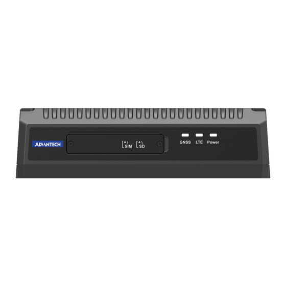
Contents Chapter General Information ......1 Introduction ....................2 Display Specifications ................2 Table 1.1: Display Specifications..........2 Box Unit Specifications ................4 Table 1.2: Box Unit Specifications..........4 Dimensions ....................6 Chapter System Setup ........7 Functional Description................8 Figure 2.1 Front View LED Indication of TREK-20 ...... 8 Table 2.1: ED Indication .............. - Page 8 TREK-20 User Manual viii...
-
Page 9: Chapter 1 General Information
Chapter General Information This chapter details general infor- mation on TREK-20. Sections include: Introduction Display Specifications Box Unit Specifications Dimensions... -
Page 10: Introduction
TREK-20 also features single cable connection between the user interface and the computing unit. It provides higher installation flexibility. 1.2 Display Specifications Table 1.1: Display Specifications Model Name TREK-20U7 7 inch UI Display TREK-203C-H000A00 Screen Diagonal Resolution (H) 1280... - Page 11 Table 1.1: Display Specifications TOP Side Buttons 7 x (w/o backlight) Power/Reset 1 x Button Programmable Key Mode 1 x Button 1/2 selection Programmable Key Lock 1 x Button Programmable Key Audio 2 x Button Level up Programmable Key Audio ...
-
Page 12: Box Unit Specifications
1.3 Box Unit Specifications Table 1.2: Box Unit Specifications Model Name Europe North America Core Unit TREK-20-ALWB1A00 TREK-20-ALWB1B00 Processor Quectel SC66-E Quectel SC66-A Memory 4GB LPDDR4X 4GB LPDDR4X Core Storage eMMC 64GB eMMC 64GB Operating System Android 10 Android 10 MicroSD (up to 128GB/ MicroSD (up to 128GB/ SD Card... - Page 13 Table 1.2: Box Unit Specifications Quantity Interface USB host 3.0 USB host 3.0 USB 3.0 Connector Standard USB Type-A USB Type-A Quantity USB OTG Interface USB OTG USB OTG (for trouble Connector USB 3.0 Type-A Standard USB 3.0 Type-A ...
-
Page 14: Dimensions
1.4 Dimensions 220.01 150.76 37.50 4-M4x0.7 L<10mm TREK-20 User Manual... -
Page 15: Chapter 2 System Setup
Chapter System Setup This chapter details system setup on TREK-20. Sections include: Functional Description Installation Procedures... -
Page 16: Functional Description
2.1 Functional Description The TREK-20, like other TREK siblings, is purpose-built for harsh environments, con- sistently featuring the reliable rugged design. Built with IP54, wide working tempera- ture (-20~60°C) fanless design, 5M3 shock & vibration, and E-mark certification, TREK-20 endures not only manufacture environments but also harsh environments like in-vehicle scenarios. - Page 17 Table 2.2: Rear I/O Indication Quantity Interface 10/100 Mbit Ethernet Connector RJ-45 with LED Indicator Quantity Interface USB Host 2.0 USB 2.0 Connector Dual Standard USB Type-A Quantity Interface USB Host 3.0 USB 3.0 Connector Standard USB Type-A ...
-
Page 18: Installation Procedures
2.2 Installation Procedures 2.2.1 Installing SIM/Micro SD Card Remove enclosed security door screw to install SIM/Micro SD Card directly. Figure 2.3 Installing SIM Card Release the security TORX M2*3L T5 screws first, then insert the SIM or Micro SD card in there. 2.2.2 Connecting Power Connect the power cord to the DC inlet of the computing box. -
Page 19: Optional Accessories Part Number List
Figure 2.4 Power Connector Outlook Table 2.4: Power Connector Signal Signal Power input (9~36V Ground Acc ignition input 2.2.3 Optional Accessories Part Number List Table 2.5: Optional Accessories Part Number Description Quantity 1700027666-01 DC-jack power cable for internal testing 1750008818-01 SMA WWAN antenna dipole 1750008765-01 FAKRA LTE/GPS (GLONASS) combo antenna, 5 m 1... - Page 20 TREK-20 User Manual...
-
Page 21: Chapter 3 I/O Connectors
Chapter I/O Connectors This chapter explains how to set up the Computing Box hardware, including instructions on setting. Sections include: I/O Connectors Pin Assignment... -
Page 22: I/O Connectors Pin Assignment
3.1 I/O Connectors Pin Assignment 3.2 Power Connector Table 3.1: Power Connector Function 9~36 V 9~36 V 9~36 V IGNITION TREK-20 User Manual... -
Page 23: High Density Connector
3.3 High Density Connector Table 3.2: IO HDC HDC DI2# HDC DO1# HDC IN2# HDC OUT2# HDC RXD HDC CTS CAN1 L HDC_USB_P HDC_USB_N D2D AGND HDC DI1# HDC_DO2# HDC IN1# HDC OUT1# HDC IN3# HDC_TXD HDC_RTS CAN1_H +V5S HDCUSB TREK-20 User Manual... -
Page 24: Audio Connector
3.4 Audio Connector Table 3.3: IO_AUDIO AUD3_C_MIC AUD3_AMP_N AUD3_C_OP_HPO AD_GND AUD3_AMP_P TREK-20 User Manual... -
Page 25: Chapter 4 Software
Chapter Software This chapter explains how to test the TREK-20. Sections include: SDK Functions Menu Display Testing... -
Page 26: Sdk Functions Content
4.1 SDK Functions Content UIO= Display control MIO= DIO/Audio control VCIL= CAN BUS control VPM= Power management SYS = System information MS-SE02_SDK_DEMO is a sample APP developed by us using SDK API. Through this APP, you will have a deeper understanding of the functions implemented by our API. -
Page 27: Di Testing
4.1.1 DI Testing Check the DI pin definition for DI testing. Select MIO (MCU /O) and go to DI functions. TREK-20 User Manual... - Page 28 Select the polling mode. Use a tweezers to short the Dl2 and GND DIO and observe the IOMCU in SDK and check if it will change status properly. TREK-20 User Manual...
-
Page 29: Do Testing
4.1.2 DO Testing Check the DO pin define for DO testing. TREK-20 User Manual... - Page 30 Select MIO (MCU I/O) and go to DO functions. Use a multimeter in beep mode and short the GND DIO and DO1 together. TREK-20 User Manual...
- Page 31 When you uncheck the DO1 you can hear the beep sauna to make sure the DO can be controled via SDK. For more functional use, please refer to the demo source code. By reading the code, you can learn how to use our API to develop your own applications. TREK-20 User Manual...
-
Page 32: Can Testing
4.1.3 CAN Testing Select VCIL and go to module settings. Setup the CAN BUS mode. TREK-20 User Manual... -
Page 33: Usb Testing
Setup the CAN BUS speed to get the CAN BUS data. 4.1.4 USB Testing Select VPM and go to SUB settings. TREK-20 User Manual... -
Page 34: How To Test Trek-20'S Rs-232 Communication Transmission
Select the USB mode that you need. 4.1.5 How to Test TREK-20’s RS-232 Communication Transmission Method: 1 Connect the high density cable to the TREK-20. TREK-20 User Manual... - Page 35 Connect a loopback to the RS-232 and install the ComPort test tool in the OS. Enter the commands below in order to access UART. 1) adb devices 2) adb root 3) adb shell 4) Setenforce 0 5) Chmod 666 dev/ttyUSB* TREK-20 User Manual...
- Page 36 Set the COM Port “/dev/ttyUSB2” and Baud Rate to “115200”. Use loopback mode to check the data can be received. TREK-20 User Manual...
- Page 37 Use common mode to send data to check if the data can be received. TREK-20 User Manual...
- Page 38 Method 2 Connect a RS-232 via USB cable to your laptop. Check if there is a USB-to serial comm port (COMxx). TREK-20 User Manual...
- Page 39 Use putty to open the COM16 and set the baud rate as “115200”. Use common mode to send data to your laptop and check if the data can be received by putty. TREK-20 User Manual...
-
Page 40: Vpm Testing (Power Management)
4.1.6 VPM Testing (Power Management) Select VPM and go to power management. Select the power mode that you needed. TREK-20 User Manual... -
Page 41: Display Testing
4.1.7 Display Testing Select UI0 and use an SDK to check if the hotkey can be triggered by a physical button. Select UI0 and go to Backlight to check if it can be adjusted by SDK. TREK-20 User Manual... - Page 42 No part of this publication may be reproduced in any form or by any means, such as electronically, by photocopying, recording, or otherwise, without prior written permission from the publisher. All brand and product names are trademarks or registered trademarks of their respective companies. © Advantech Co., Ltd. 2024...
Need help?
Do you have a question about the TREK-20U7 and is the answer not in the manual?
Questions and answers