
Subscribe to Our Youtube Channel
Related Manuals for Advantech TouchMix XI


Summary of Contents for Advantech TouchMix XI
-
Page 1: User Manual
Computer User Manual Version 1.0 TouchMix ® XI Computer User Manual Date: 6/10/16 Doc#: 2005SA1800 ... -
Page 2: Table Of Contents
Table of Contents Preface ............................ 3 CE Conformity Statement...................... 3 Copyright Statement ........................ 4 Safety Information ........................ 5 Basic Safety Instructions ...................... 5 Certifications .......................... 7 Hazardous Location ‐ Installation Control Drawings .............. 9 USA and Canada Installations: ..................... 1 4 ATEX (EU) Installations: ...................... 1 6 IECEx Installations: ....................... 1 7 Exploring the TouchMix® XI Computer .................. 2 1 ... -
Page 3: Preface
Preface CE Conformity Statement IEC 60950-1 (EN 60950-1) Product Safety This product has passed testing. Test conditions included the recommended power supplies. In order to protect the product from ESD (Electrostatic Discharge) damage and EMI leakage, we strongly recommend the use of CE‐compliant devices when connecting to the product. FCC Compliance Statement This device complies with part 15 of the FCC Rules. Operation is subject to the following two conditions: 1. This device may not cause harmful interference; 2. -
Page 4: Copyright Statement
All described herein shall not be distributed, modified, reverse engineered, or reproduced in any manner without the prior permission of Advantech Co. or of the other third parties, to whom the software rights belong. All other product names, trademarks or logos mentioned herein and are the property of their respective owners. -
Page 5: Safety Information
Safety Information Sensitive to Static Discharge! Always ground yourself to remove any static charge before touching the CPU board. Modern electronic devices are very sensitive to static electric charges. As a safety precaution, use a grounding wrist strap at all times. Place all electronic components in a static-dissipative surface or static-shielded bag when they are not in the chassis. - Page 6 If the equipment is not used for a long period of time, disconnect it from the power source to avoid being damaged by stray transient over voltages. CAUTION: RISK OF EXPLOSION IF INTERNAL COIN CELL BATTERY IS INCORRECTLY REPLACED. REPLACE ONLY WITH SAME OR EQUIVALENT TYPE AS RECOMMENDED BY THE MANUFACTURER.
-
Page 7: Certifications
Certifications IEC60950-1 General Safety ® TouchMix XI Computer User Manual Date: 6/10/16 Doc#: 2005SA1800 Page 7... - Page 8 ® TouchMix XI Computer User Manual Date: 6/10/16 Doc#: 2005SA1800 Page 8...
-
Page 9: Hazardous Location - Installation Control Drawings
Hazardous Location - Installation Control Drawings The following drawings provide the minimal requirements for installation of the computer system into a hazardous environment. These drawings cover North America (USA& Canada), ATEX (EU), and IECEx Installation sites. Additional local requirements may apply. It is the end users responsibility to make sure the installation complies with all applicable local, national, and international requirements. - Page 10 Hazardous Location Certificates: North America ® TouchMix XI Computer User Manual Date: 6/10/16 Doc#: 2005SA1800 Page 10...
- Page 11 ® TouchMix XI Computer User Manual Date: 6/10/16 Doc#: 2005SA1800 Page 11...
- Page 12 ATEX ® TouchMix XI Computer User Manual Date: 6/10/16 Doc#: 2005SA1800 Page 12...
- Page 13 IECEx ® TouchMix XI Computer User Manual Date: 6/10/16 Doc#: 2005SA1800 Page 13...
-
Page 14: Usa And Canada Installations
USA and Canada Installations: Refer to Figure 1: 1) System installation must be made in accordance with the National Electrical Code® (NEC), NFPA 70, Article 500, 501, 504 and 505 and ANSI / ISA-RP12.6; and in Canada with the Canadian Electrical Code® (CEC), Part 1, Section18, as well as all applicable local codes. 2) In the USA, the computer must be connected to a suitable ground electrode per NEC NFPA 70, Article 500, 501, 504 and 505. - Page 15 USA: Class I, Division 2, Group C, D T4 Class I, Zone 2, AEx nA [iC] IIB T4 CAN: EX nA [iC] IIB T4 Class I, Division 2, Group C, D T4 Figure 1 TouchMix ® XI Computer User Manual Date: 6/10/16 Doc#: 2005SA1800 Page 15...
-
Page 16: Atex (Eu) Installations
ATEX (EU) Installations: Refer to Figure 2: 1) System installation must be made in accordance with IEC60079-14, as well as all applicable local codes. 2) The computer must be connected to a suitable ground electrode per all applicable local codes. 3) All connections to the computer shall only be made / broken when the unit is powered off. - Page 17 Figure 2 TouchMix ® XI Computer User Manual Date: 6/10/16 Doc#: 2005SA1800 Page 17...
-
Page 18: Iecex Installations
IECEx Installations: Refer to Figure 3: 1) System installation must be made in accordance with IEC60079-14, as well as all applicable local codes. 2) The computer must be connected to a suitable ground electrode per all applicable local codes. 3) All connections to the computer shall only be made / broken when the unit is powered off. All connectors shall be secured with the provisions supplied by the manufacturer to prevent unintentional disconnection during operation. - Page 19 Figure 3 TouchMix ® XI Computer User Manual Date: 6/10/16 Doc#: 2005SA1800 Page 19...
- Page 20 Page intentionally left blank TouchMix ® XI Computer User Manual Date: 6/10/16 Doc#: 2005SA1800 Page 20...
-
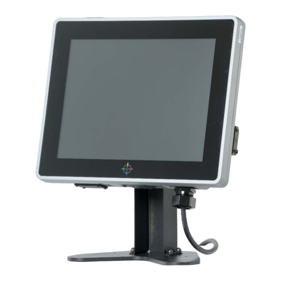
Page 21: Exploring The Touchmix® Xi Computer
Exploring the TouchMix® XI Computer TouchMix ® XI Computer User Manual Date: 6/10/16 Doc#: 2005SA1800 Page 21... -
Page 22: Installing The Wi-Fi Module
Installing the Wi-Fi Module 1) Unscrew the Wi-Fi cover, revealing gasket and USB port: 2) Prepare Wi-Fi module and foam seal (in Accessory Box) as follows: Orient parts as shown Slide Wi-Fi Module into foam as shown 3) Insert the Wi-Fi module into the top USB port of the TouchMix® XI computer. Re- secure the Wi-Fi cover with screws. -
Page 23: Opening The Back Cover
Opening the Back Cover Loosen all eight screws, as indicated below. NOTE: These are captured screws – do not remove from cover TouchMix ® XI Computer User Manual Date: 6/10/16 Doc#: 2005SA1800 Page 23... -
Page 24: Mounting And Cable Fittings
Mounting and Cable Fittings: Safe Area Cable Connections The TouchMix® XI computer allows for cable connections to a safe area via a conduit attached to the housing. For USA & Canadian installations, the computer housing provides a single conduit opening able to accept a standard "Ex" certified conduit fitting. For ATEX/IECEx installations any suitable ATEX/IEC approved cable gland is to be used. -
Page 25: Non-Energy Limited (Safe Area) Connections
NON-ENERGY LIMITED (Safe Area) Connections 5 2 3 4 1 (1) 12VDC Power Supply Connection Use supplied DC power cable and cable exit gland. Reference Installation Control Drawings) Pin Number Signal Name 12VDC... - Page 26 Standard Power Supply Standard DC cable b.) Optional ATEX approved Power Supply (ATEX Installations ONLY) Mount ATEX power supply in the hazardous area as required. Connect the DC cord to the TouchMix® XI Computer DC power input and route to ATEX power supply and connect to Power Supply connector. Route AC cord to Safe Area via appropriate means (see Installation Control Drawings) – DO NOT CONNECT AC Mains until all connections to the computer have been completed! Optional ATEX Power Supply TouchMix ®...
- Page 27 Optional ATEX Cable Power Cable Installation ‐ The TouchMix® XI computer includes a hardened power cable and metal cable gland that must be installed prior to final mounting of the computer. Step 1 – Remove Back cover as described above. Push rubber shipping plug out from the inside. TouchMix ® XI Computer User Manual Date: 6/10/16 Doc#: 2005SA1800 Page 27...
- Page 28 Step 2 – Prepare power cable and cable gland components as illustrated. Make sure the power cable is oriented to have the correct connector as shown. Step3 – Slip power cable in to gland parts in the order shown. Start with the nut, then slip the rubber seal onto cable by spreading open the slit in the rubber piece and slide over cable, then slip on the threaded fitting (seal towards connector). Step 4 – Slide Power connector into the computer housing as shown. Use care to align connector key when inserting (key facing up towards installer). Secure by tightening the nut. TouchMix ® XI Computer User Manual Date: 6/10/16 Doc#: 2005SA1800 Page 28...
- Page 29 Step 5 – Screw gland fitting into housing. Make sure threads are aligned and the fitting does not bind while tightening. Do not over tighten fitting as this may damage the seal. The seal between may not be deformed. Step 6 – Slide rubber plug into the fitting and push in as far as possible by hand. TouchMix ® XI Computer User Manual Date: 6/10/16 Doc#: 2005SA1800 Page 29...
- Page 30 Step 7 — Slide nut onto fitting and tighten to create a tight squeeze on the cable. NON‐ENERGY LIMITED (Safe Area) CONNECTIONS Continued (2) USB 2.0 Port Reference Installation Control Drawings and local codes for connections. (3) Dedicated USB Port for Memory Stick (Installed at factory) Consult your retailer for an appropriate replacement. TouchMix ® XI Computer User Manual Date: 6/10/16 Doc#: 2005SA1800...
- Page 31 (4) HDMI Video Port Reference Installation Control Drawings and local codes for connections. (5) Ethernet Port Reference Installation Control Drawings and local codes for connections. TouchMix ® XI Computer User Manual Date: 6/10/16 Doc#: 2005SA1800 Page 31...
-
Page 32: Energy Limited (Hazardous Area) Connections
ENERGY LIMITED (Hazardous Area) Connections "Non‐lncendive Field Wiring Connections for Class I, Division 2, Group(s)" ALL ports marked with MUST comply with the Entity Parameters provided in the tables below. Internal connections: Internal energy limited USB and Serial to be used ONLY for hazardous location approved scales. Serical connection USB connection Use the supplied cover with hole ... - Page 33 (1) RS232 Serial Port (Dedicated for scale) Requires end user supplied cable for installation. (Reference Installation Control Drawings) IMPORTANT ‐ ALL connections to these ports MUST comply with the Entity Parameters provided below. Note ‐ Cable capacitance and inductance must be included in the overall connection calculations. Worst case capacitance and inductances generally accepted are: Capacitance‐197pF/m (60pF/ft.) and Inductance‐0.66uH/m (0.20uH/ft.) Vmax (or Ui) > Voc (or Uo) Imax (or Ii) > Isc (or Io) Pi > Po Ci + Ccable < Ca (or Co) Li + Lcable < La (or Lo) Entity Parameters for RS‐232 (Dedicated Scale port) Pin Signal Name (In/Out): Voc/Uo= Isc/Io= Number: (uF) (mH) Pin 1 ...
- Page 34 (2) USB2.0 Port (Dedicated for scale) Requires end user supplied cable for installation. (Reference Installation Control Drawings) IMPORTANT ‐ ALL connections to these ports MUST comply with the Entity Parameters provided below Note ‐ Cable capacitance and inductance must be included in the overall connection calculations. Worst case capacitance and inductances generally accepted are: Capacitance‐197pF/m (60pF/ft.) and Inductance‐0.66uH/m (0.20uH/ft.) Vmax (or Ui) > Voc (or Uo) Imax (or Ii) > Isc (or Io) Pi > Po Ci + Ccable < Ca (or Co) Li + Lcable < La (or Lo) Entity Parameters for USB 2.0 (Dedicated Scale port) Pin Signal Name (In/Out): Voc/Uo= Isc/Io= Number: (uF) (mH) Pin 1 Power 11.6 1.302 3.776 0.03 Pin 2...
- Page 35 Side mounted USB 2.0 Port - Approved for USB Memory use ONLY! Side Connection: To be used with USB Memory ONLY, no other devices are allowed. Loosen capture screw (A) and flip the door up to insert USB drive. A When not in use, this cover must be secured with the screw. ...
- Page 36 Entity Parameters for USB 2.0 (Side USB port) Pin Signal Name (In/Out): Voc/Uo= Isc/Io= Number: (uF) (mH) Pin 1 Power 11.6 1.302 3.776 0.03 Pin 2 Data – (bidirectional) 0.673 1.683 0.25 Pin 3 Data + (bidirectional) 0.673 1.683 0.25 Pin 4 ‐‐‐ ‐‐‐ ‐‐‐ ‐‐‐ ‐‐‐ Note ‐ Cable capacitance and inductance must be included in the overall connection calculations. Worst case capacitance and inductances generally accepted are: Capacitance‐197pF/m (60pF/ft.) and Inductance‐0.66uH/m (0.20uH/ft.) Vmax (or Ui) > Voc (or Uo) Imax (or Ii) > Isc (or Io) Pi > Po Ci + Ccable < Ca (or Co) Li + Lcable < La (or Lo) ...
-
Page 37: Additional Safety Features
Additional Safety Features Equipment Grounding Connection The grounding screw terminal is located on the back lower right corner of the computer. Consult Installation Control Drawings for connection requirements. TouchMix ® XI Computer User Manual Date: 6/10/16 Doc#: 2005SA1800 Page 37... - Page 38 Back Cover Power Interlock Switch This switch disables the computer when the Back cover is open. Make sure all Back cover screws are securely fastened. TouchMix ® XI Computer User Manual Date: 6/10/16 Doc#: 2005SA1800 Page 38...
-
Page 39: Closing Back Cover
Closing Back Cover Once all of the connections have been made, reseat the Back cover and secure with all eight (8) retaining screws held in the cover. Caution: Before closing, check that the Back cover seal is fully seated into groove around both connection areas. -
Page 40: Computer Mounting (Wall, Pole, Or Stand)
Computer Mounting (Wall, Pole, or Stand) The computer is able to be mounted to any wall, pole, or stand mount via the industry standard VESA mount pattern on the rear face of the computer. Pattern: VESA 75 x 75mm or 100 x 100mm ... -
Page 41: Power
Power On Ensure the Back cover is installed and secured with screws. Press the button, on the back lower right (when viewing computer from the screen side). When powered on, the LED light on the button turns green. TouchMix ® XI Computer User Manual Date: 6/10/16 Doc#:... -
Page 42: Maintenance
Maintenance Note: There are no user serviceable parts inside the computer. Cleaning the TouchMix XI Computer Screen ® 1. Turn off the TouchMix® XI Computer and unplug the power cord. 2. Wipe the screen and exterior with a soft cloth. 3. -
Page 43: Appendix
Appendix Specifications General Manufacturer: Advantech, Corp. Model No: DMS-SA18 Dimensions (W x H x D): 390mm x 314mm x 60mm Chassis material: Aluminum-Alloy Die Castings Mounting: VESA mount Input voltage: 12VDC/3.7A OS Support: Windows 8 Embedded Standard ...
Need help?
Do you have a question about the TouchMix XI and is the answer not in the manual?
Questions and answers