Table of Contents
Advertisement
Quick Links
Instructions-Parts
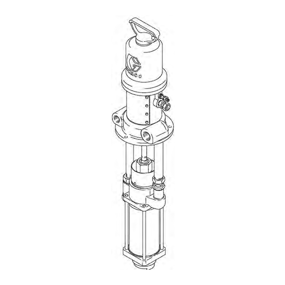
2:1 Ratio Monark®
Pump
Used for transfer, supply, and recirculation of compatible fluids. For professional use only.
200 psi (1.4 MPa, 14 bar) Maximum Fluid Working Pressure
100 psi (0.7 MPa, 7 bar) Maximum Air Input Pressure
Part No. 223185, Series C
55 Gallon (200 Liter) Drum Size, UHMWPE and Leather
Packed
Part No. 223186, Series C
Stubby Size, UHMWPE and Leather Packed
See page 3 for model information, including maximum
working pressure and approvals.
Important Safety Instructions
Read all warnings and instructions in this
manual before using the equipment. Be
familiar with the proper control and
usage of the equipment. Save these
instructions.
307985N
EN
Advertisement
Table of Contents

Related Manuals for Graco Monark 223185


Summary of Contents for Graco Monark 223185
- Page 1 Instructions-Parts 2:1 Ratio Monark® Pump 307985N Used for transfer, supply, and recirculation of compatible fluids. For professional use only. 200 psi (1.4 MPa, 14 bar) Maximum Fluid Working Pressure 100 psi (0.7 MPa, 7 bar) Maximum Air Input Pressure Part No. 223185, Series C 55 Gallon (200 Liter) Drum Size, UHMWPE and Leather Packed Part No.
-
Page 2: Table Of Contents
Technical Specifications ....19 Graco Standard Warranty ....20... -
Page 3: Models
Models Models Maximum Working Part Series Pressure Description Approvals psi (MPa, bar) Stubby Size, UHMWPE and 223186 Leather Packed 200 (1.4, 14) 55 Gallon (200 Liter) Drum 223185 Size, UHMWPE and Leather Packed 307985N... -
Page 4: Warnings
Warnings Warnings The following warnings are for the setup, use, grounding, maintenance, and repair of this equipment. The exclamation point symbol alerts you to a general warning and the hazard symbols refer to procedure-specific risks. When these symbols appear in the body of this manual or on warning labels, refer back to these Warnings. Product-specific hazard symbols and warnings not covered in this section may appear throughout the body of this manual where applicable. - Page 5 Warnings WARNING MOVING PARTS HAZARD Moving parts can pinch, cut or amputate fingers and other body parts. • Keep clear of moving parts. • Do not operate equipment with protective guards or covers removed. • Equipment can start without warning. Before checking, moving, or servicing equipment, follow the Pressure Relief Procedure in page 9 and disconnect all power sources.
-
Page 6: Installation
NOTE: Reference numbers and letters in parentheses in the text refer to the callouts in the figures and the parts drawing. NOTE: Always use Genuine Graco Parts and Accessories, available from your Graco distributor. If you supply your own accessories, be sure they are adequately sized and pressure rated for your system. -
Page 7: Mounting The Pump
Installation Mounting the Pump Mount the pump to suit the type of installation planned. If the pump is mounted on the wall or on a stand, Refer the Dimensions and Mounting, page 17, connect a suction line to the pump’s 1–1/2 in. npt(f) fluid section. -
Page 8: Available Accessories
Installation Available Accessories (must be purchased separately) Air Line Accessories Fluid Line Accessories A bleed-type master air valve (A) is required in your A fluid drain valve (D) is required in your system to system to help reduce the risk of serious injury, help reduce the risk of serious injury, including including splashing of fluid in the eyes or on the skin, splashing of fluid in the eyes or on the skin. -
Page 9: Operation
Operation Operation Pressure Relief Procedure Packing Nut Follow the Pressure Relief Procedure whenever you see this symbol. Check the tightness of the packing nut/wet-cup (U) periodically. The nut should be tight enough to prevent leakage. Torque the nut to 20--24 ft-lb (27--33 N.m); do This equipment stays pressurized until pressure is not over tighten or you may damage the packings. -
Page 10: Flush The Pump Before First Use
Operation Flush the Pump Before First Use 10. Release the gun trigger and lock the trigger safety. In a circulating system, the pump will run The pump is tested with lightweight oil, which is left in to continuously and slow down or speed up on protect the pump parts. -
Page 11: Maintenance
Maintenance Maintenance Check with your fluid manufacturer or supplier for recommended flushing fluids and flushing frequency. NOTICE Never leave water or water-base fluid in the pump overnight. If you are pumping water-base fluid, flush with water first, then with a rust inhibitor such as mineral spirits. -
Page 12: Troubleshooting
Troubleshooting Troubleshooting 1. Follow the Pressure Relief Procedure on page 9. 2. Check all possible problems and solutions before disassembling pump. Problem Cause Solution Pump fails to operate. Restricted line or inadequate air Clear; increase air supply. supply. Dirty or damaged air motor. Service air motor (see 307043). -
Page 13: Repair
Repair Repair Reconnecting the Displacement Pump 1. Position the displacement pump on the mounting tubes (11, 12). Thread the upper locknut (9) onto the return mounting tube (11) a couple of turns. Tighten the swivel union (S) securely onto the supply mounting tube (12). - Page 14 Repair Torque to 65–75 ft-lb (88–102 N.m). Use thread sealant when reinstalling. Lubricate. . 4: Connecting the Displacement Pump 307985N...
-
Page 15: Parts
Parts Parts Model 223185, Series C 2:1 Ratio Monark Pump, 55 Gallon (200 Liter) Drum Size; UHMWPE and Leather Packed Ref. Part Description Qty. Used on Models 223185 only. 206955 AIR MOTOR, Monark; see 307043 for parts 223177 PUMP, displacement; used on Model 223185;... - Page 16 Parts Model 223186, Series C 2:1 Ratio Monark Pump, Stubby Size; UHMWPE and Leather Packed Ref. Part Description Qty. 206955 AIR MOTOR, Monark; see 307043 for parts 223177 PUMP, displacement; used on Model 223185; see 307983 for parts 191736 ROD, connecting; 100579 PIN, cotter 118160 LOCKWASHER, ext shakeproof 156082 O-RING;...
-
Page 17: Dimensions And Mounting
Dimensions and Mounting Dimensions and Mounting Dimensions Mounting Hole Layouts Model No. 223185 47.81 1215 15.31 389 32.5 223186 35.31 897 15.31 389 307985N... -
Page 18: Performance Charts
Performance Charts Performance Charts KEY: Fluid Outlet Pressure - Black Curves Air Consumption - Gray Curves. A 100 psi (7 bar) air pressure B 70 psi (4.9 bar) air pressure C 40 psi (2.8 bar) air pressure To find Fluid Outlet Pressure (bar/psi) at a specific To find Pump Air Consumption (m#/min or scfm) at a fluid flow (lpm/gpm) and operating air pressure (bar/psi): specific fluid flow (lpm/gpm) and operating air pressure... -
Page 19: Technical Specifications
Technical Specifications Technical Specifications Category Metric Ratio 200 psi 14 bar Maximum fluid working pressure 100 psi 7 bar Maximum air input pressure Pump cycles per 1 gallon (3.8 liters) 5.5 gpm 21 liters/min Fluid flow at 60 cycles per minute 1–1/2 npt(f) Fluid inlet size 1 in. -
Page 20: Graco Standard Warranty
With the exception of any special, extended, or limited warranty published by Graco, Graco will, for a period of twelve months from the date of sale, repair or replace any part of the equipment determined by Graco to be defective.
Need help?
Do you have a question about the Monark 223185 and is the answer not in the manual?
Questions and answers