Advertisement
Quick Links
INSTRUCTIONS-PARTS LIST
This manual contains IMPORTANT
WARNINGS AND INSTRUCTIONS
READ AND RETAIN FOR REFERENCE
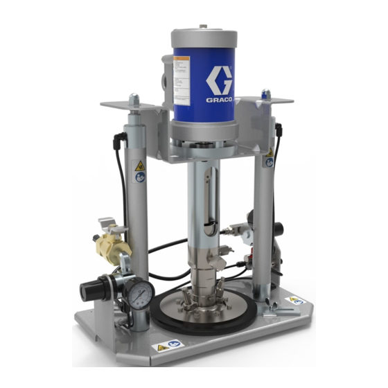
8.5:1 RATIO
DYNAMITE
60 bar (850 psi) MAXIMUM FLUID WORKING PRESSURE
7 bar (100 psi) MAXIMUM AIR INLET PRESSURE
Model 223-847, Series A
Includes Pump, Ram, and 1 Gallon Wiper Plate
Model 223-848, Series A
Includes Pump, Ram, and 3 Kilogram Wiper Plate
Model 223-849, Series A
Includes Pump, Ram, and 1 Quart Wiper Plate
Model 223-850, Series A
Includes Pump, Ram, and 1 Kilogram Wiper Plate
TABLE OF CONTENTS
. . . . . . . . . . . . . . . . . . . . . . . . . . . . . . . .
. . . . . . . . . . . . . . . . . . . . . . . . . . . .
Operation-Maintenance
. . . . . . . . . . . . . . . . . . . . . . . . . .
Pump Service
. . . . . . . . . . . . . . . . . . . . . . . . .
. . . . . . . . . . . . . . . . . . . . . . . . . . . .
Technical Data
. . . . . . . . . . . . . . . . . . . . . . . . . .
Performance Chart
. . . . . . . . . . . . . . . . . . . . . .
. . . . . . . . . . . . . . . . . . . .
. . . . . . . . . . . . . . . . . . . . . . .
Toll-Free Graco Phone Numbers
Hazard of Using Fluids Containing Halogenated Hydrocarbons
Never use 1,1,1-trichloroethane, methylene chloride, other halogenated hydrocarbon solvents or fluids containing
such solvents in this equipment. Such use could result in a serious chemical reaction, with the possibility of explosion,
which could cause death, serious bodily injury and/or substantial property damage.
Consult your fluid suppliers to ensure that the fluids used are compatible with aluminum and zinc parts.
GRACO INC. P.O. BOX 1441 MINNEAPOLIS, MN 55440-1441
190 PUMP
TM
2
3, 4
. . . . . . . . . . . . . . . . .
5, 6
7
8-10
. . . . . . . . . . . . . .
11-16
17
18
18
19
Back Cover
. .
Back Cover
COPYRIGHT 1990, GRACO INC.
WARNING
308-051
Rev B
Supersedes A
MODEL 223-847 SHOWN
Advertisement

Related Manuals for Graco DYNAMITE 190 A Series


Summary of Contents for Graco DYNAMITE 190 A Series
-
Page 1: Table Of Contents
Consult your fluid suppliers to ensure that the fluids used are compatible with aluminum and zinc parts. GRACO INC. P.O. BOX 1441 MINNEAPOLIS, MN 55440–1441 COPYRIGHT 1990, GRACO INC. - Page 2 Do not use fluids which are not compatible with the in- ner tube and cover of the hose. DO NOT expose Graco hoses to tem- peratures above 82 C (180 F) or below –40 C (–40 F).
-
Page 3: Warnings
(125). These devices help re- duce the risk of serious bodily injury including Contact your Graco representative or Graco T echnical splashing in the eyes or on the skin, and injury from Assistance (1–800–543–0339) for assistance in design- moving parts if you are adjusting or repairing the ing a system to suit your particular needs. - Page 4 Pump Fluid Intake Housing 227b Ram Air Regulator Pump Bleeder Valve Ram Director Valve Fluid Outlet Fitting Wing Screws Bleed–Type Master Air Valve Air Inlet Air Assist Valve (Pushbutton) Air Line to Wiper Plate Clamps Wiper Plate Assembly 227a Pump Air Regulator Wiper Bleed Valve 227a 227b...
- Page 5 OPERATION which the ram raises and lowers, adjust the air regu- WARNING lator to increase or decrease the air volume. Pressure Relief Procedure To reduce the risk of serious bodily injury, including 3. Check that the fluid can is not dented or out of shape, fluid splashing in the eyes or on the skin, or injury which will damage the wiper plate and cause leakage from moving parts, always follow this procedure...
- Page 6 Shutdown and Care of the Pump 3. Shut off the air supply to the ram and pump and follow the Pressure Relief Procedure W arning on page 1. Always flush the pump with a compatible solvent be- fore fluid dries in the pump. 2.
-
Page 7: Troubleshooting
TROUBLESHOOTING CHART PROBLEM CAUSE SOLUTION Clear; see TECHNICAL DATA on page 18. Pump does not operate. Restricted air line, clogged air passages, or inadequate air supply. Main air valve is closed. Open. Air regulator malfunction. Replace. Dirty or worn air motor parts; air motor leak. Clean and overhaul air motor. - Page 8 SERVICE DISASSEMBLY 9. Pull the priming piston rod (110) and fluid piston (106) straight up out of the fluid housing (109). Remove the NOTE: Repair Kit 223–895 is available to repair the air pin (123), and unscrew the priming piston rod from motor.
- Page 9 162** 103b* 103d* TORQUE TO 35–37 N.m (298–314 in–lb) 163** TORQUE LIPS BLEED HOLE MOUNTING MUST MUST FACE SCREWS FACE DOWN TO 2–4 N.m DOWN (17–33 in–lb) *166 TORQUE TO 0.4–0.6 N.m (4–6 in–lb) TORQUE TO 35–37 N.m (298–314 in–lb) **161 **114 *103c...
- Page 10 8. Install the two small o–rings (103b*) in the grooves of the air motor piston (104). Secure the cylinder to the the inner diameter of the air motor piston (104). Low- coupling with three screws (138) and washers (141). er the piston through the air motor coupling (105) so it Torque the screws to 2–4 N.m (17–33 in–lb).
- Page 11 2. Check the parts list to identify the correct part number; do not use RAM ASSY (not sold separately) the ref. no. when ordering. See pages 14 and 15 for parts 3. Order all parts from your nearest Graco distributor. 223–851 WIPER PLATE ASSY, 1 gallon size 6 digit (Used on Model 223–847)
- Page 12 PARTS DRAWING (PUMP ASSEMBLY) STANDARD FLUID OUTLET FITTING 166–866 IS 1/4 npt(f). OPTIONAL FITTING 186–475, SUPPLIED WITH 3 kg AND 1 kg WIPER PLATE ASSEMBLIES 223–852 AND 223–854, IS 1/4 PT–19(f). 162** 103b* TORQUE TO 35–37 N.m (298–314 in–lb) 103d* 163** LIPS TORQUE...
- Page 13 2. Check the parts list to identify the correct part number; do not use the ref. no. when ordering. 3. Order all parts from your nearest Graco distributor. 6 digit Part Number Part Description...
- Page 14 PARTS DRAWING (RAM ASSEMBLY) REFERENCE LETTERS A, B, C AND D REFER TO HOSE CONNECTIONS PUMP ASSEMBLY (SEE PAGE 12) 141 (REF) 138 (REF) 279 (REF) 278 (REF) PART OF PUMP ASSEMBLY 275 (REF) (SEE PAGE 12) TORQUE TO (SEE 0.4–0.6 N.m PAGE 16) (4–6 in–lb)
- Page 15 2. Check the parts list to identify the correct part number; do not use the ref. no. when ordering. 3. Order all parts from your nearest Graco distributor. 6 digit Part Number Part Description...
-
Page 16: Parts Drawings And Lists
2. Check the parts list to identify the correct part number; do not use 10 mm long the ref. no. when ordering. 223–746 VALVE, bleed, wiper plate 3. Order all parts from your nearest Graco distributor. 186–546 RING, backup; carbon steel 6 digit 186–457 RING, wiper;... -
Page 17: Accessories
ACCESSORIES USE GENUINE GRACO PARTS AND ACCESSORIES Must be purchased separately . POLYURETHANE CONVERSION KIT 223–939 AIR LINE LUBRICATOR 110–148 Converts u–cup throat packing to polyurethane. 21 bar (300 psi) MAXIMUM WORKING PRESSURE Consists of: .030 liter (1 oz) bowl capacity; 1/4 npt(f) inlet and outlet Part No. - Page 18 TECHNICAL AND PERFORMANCE DATA Maximum fluid working pressure ........60 bar (850 psi) Air input pressure range .
-
Page 19: Dimensional Drawing
DIMENSIONAL DRAWING LOWERED: 416 mm (16.38 in.) RAISED: 650 mm (25.6 in.) 1/4 npt(f) AIR INLET 1/4 npt(f) FLUID OUTLET (STANDARD) BASE: 250 mm (9.85 in.) 245 mm (9.65 in.) INCLUDING AIR REGULATORS AND CLAMPS WHEN USED WITH 1 GALLON CAN: 320 mm (12.6 in.) OPTIONAL FLUID OUTLET FITTING SUPPLIED WITH 3 kg AND 1 kg WIPER PLATE ASSEMBLIES... -
Page 20: Warranty
Graco distributor to the original purchaser for use. As purchaser’s sole remedy for breach of this warranty, Graco will, for a period of twelve months from the date of sale, repair or replace any part of the equipment proven defective.
Need help?
Do you have a question about the DYNAMITE 190 A Series and is the answer not in the manual?
Questions and answers