Table of Contents
Advertisement
New Product
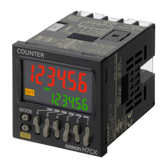
Multifunction Counter/Tachometer
H7CX-@
-N
Ultra-compact Counter Provides More
Complete Functionality.
Basic Features
• Short body with depth of only 59 mm (for 12 to 24-VDC Models with Screw
*1
Terminals).
• Better readability with character height of 12 mm on 4-digit models and 10 mm
on 6-digit models.
• The present value display characters can be switched between red, green, and
*2
orange.
Safety and Reliability
• New set value limit and counter functions have been added.
• Front Panel can be changed to white or light gray.
• Models with two independent tachometer inputs have been added to the series.
*1.For 100 to 240-VAC Models with Screw Terminals: 78 mm, Models with Sockets: 63.7 mm (case dimension).
*2.The H7CX-A11 and H7CX-R11 have only red characters.
*3.The Front Panel can be replaced with an optional Front Panel (except for Tachometer-only Models).
Features
Basic Features
Ultra Short Body
The body depth has been greatly reduced. Helps in making thinner
control panels.
12 to 24-VDC Models with Screw Terminals: 59 mm
100 to 240-VAC Models with Screw Terminals: 78 mm*
Models with Sockets: 63.7 mm (case dimension)
* Power supply circuit and input circuits are isolated for safety and reliability.
New models
Easier to Read
For better readability, the character height for the present value
display is 12 mm on models with 4 digits, the largest class in the
industry. The wide viewing angle and brightness provide excellent
visibility. The number of display segments has also been increased to
make settings easier to understand, and the present value display
can be switched between red, green, and orange so that output status
can be seen from a distance.
Model with 4 Digits Model with 6 Digits
12 mm
10 mm
(actual size)
(actual size)
(Display example)
Note: The display color can be switched on all models except for the
H7CX-A11 and H7CX-R11.
The Easiest Operation
Operation is simplified by the
Model with 4 Digits
Up/Down Key for each digit
on 4-digit models and Up
Key for each digit on 6-digit
models.
*3
Previous
models
New
Previous
models
models
Easy to read from the top, bottom,
and sides!
Model with 6 Digits
Refer to Safety Precautions on page 52.
Safety and Reliability
Isolated Power Supply and Input Circuits
Power supply circuit and input circuits are isolated inside the Counter/
Tachometer. Previous non-isolated counters had wiring restrictions
and could be damaged if wired incorrectly. The H7CX removes these
worries.
Note: Except 12 to 24-VDC models.
Set Value Limit
You can set an upper limit for the set value to prevent unexpected
operation of output devices caused by setting mistakes.
Setting the upper limit of the set
value enables worry-free operation.
No overflow
For 1,000 pieces
Output Counter
The output counter counts the number of times the output turns ON
(alarms can be displayed and the count can be monitored in
increments of 1,000 operations). This counter is useful in managing
the service life of the Counter/Tachometer or the load.
1
Advertisement
Table of Contents

Related Manuals for Omron H7CX-N


Summary of Contents for Omron H7CX-N
-
Page 1: Basic Features
• Front Panel can be changed to white or light gray. • Models with two independent tachometer inputs have been added to the series. *1.For 100 to 240-VAC Models with Screw Terminals: 78 mm, Models with Sockets: 63.7 mm (case dimension). *2.The H7CX-A11 and H7CX-R11 have only red characters. -
Page 2: Other Features
11-pin socket Display color of present value Red, green, or orange Display digits 4 or 6 digits 4 digits 6 digits 6 digits *1. Set the tachometer input mode from the function setting mode to switch to the tachometer function. -
Page 3: Ordering Information
Contact output (SPDT + SPST) 12 to 24 VDC/24 VAC H7CX-R11WD1-N outputs) Note: 1. The functions that are provided depend on the model. Check detailed specifications before ordering. 2. Refer to page page 37 and later for information on H7CX-R Tachometers. - Page 4 Y92P-CXC6B Black (N1.5) Note: 1. You can change the color of the Front Panel when mounting the Counter. The Counter is shipped with a black (N1.5) Front Panel. 2. "COUNTER" is printed on the front of Replacement Front Panels. Soft Cover...
-
Page 5: Specifications
*2. Do not use the output from an inverter as the power supply.The ripple must be 20% maximum for DC power. *3. A response of 10 kHz is possible if the response speed is 5 kHz and the 1-stage preset counter input mode is increment, decrement, or increment/ decrement (command input). - Page 6 H7CX-A4@-N H7CX-AW@-N/-AU@-N H7CX-A@-N Item H7CX-A4W@-N Selectable from independent measurements for 1 or 2 inputs, differential input for 2 inputs, absolute ratio for 2 inputs, and Input mode error ratio for 2 inputs. Pulse measurement method Periodic measurement Pulse width measurement...
- Page 7 *1. For information on operation of I/O functions, refer to pages page 22 to page 25. *2. In increment mode or increment/decrement mode, the present value returns to 0; in decrement mode, the present value returns to the set value with 1-stage models, and returns to set value 2 with 2-stage models.
-
Page 8: Terminal Arrangement
Transistor Output • The transistor output of the H7CX is isolated from the internal • The diode connected to the collector of the output transistor is used circuitry by a photocoupler, so the transistor output can be used as to absorb inverted voltage that is generated when an inductive load both NPN and PNP output. -
Page 9: Block Diagram
Note: All models except for H7CX-@D-N have basic insulation. circuit Internal circuit Input Connections The inputs of the H7CX-@-N are no-voltage (short-circuit or open) inputs or voltage inputs. No-voltage Inputs (NPN Inputs) Open Collector Voltage Output Contact Input DC Two-wire Sensor... - Page 10 OUT: (Two-stage) 12. Up Keys 3. Reset Indicator (orange) (6-digit models: (Lit when the reset input (1) or Reset Key is ON.) Displayed only when the configuration selection 13. Down Keys mode is not tachometer mode. 4th digit 1st digit 4.
- Page 11 Y92S-29 (order separately) Panel Y92F-30 (order separately) Dimensions with Front Waterproof Packing Flush Mounting Adapter Connecting Socket (51) H7CX -A11@ 100.9 103.2* 89.9 P2CF-11(-E) Front Connecting Socket (order separately) * These dimensions depend on the kind of DIN Track. (Reference value)
- Page 12 Replacement Front Panels. The H7CX's panel surface is water-resistive (conforming to IP@6, Y92P-CXC4G UL Type 4X) and so even if drops of water penetrate the gaps 4-digit Counter between the keys, there will be no adverse effect on internal circuits.
- Page 13 Note: A Y92A-48G Terminal Cover can be used with the Socket to create a finger-safe construction. Terminal Covers for P3GA-11 Back-connecting Socket Model Dimensions Y92A-48G Twelve, 6.4-dia. holes 47.7 47.7 Y92A-48G 16.5 24.6 27.6 47.4 Note: The Terminal Cover can be used with a Back-mounting Socket (P3GA-11) to create a finger-safe construction.
- Page 14 1,000 (500)* * The values shown in parentheses are for the PFP-50N. Mounting Track PFP-100N2 29.2 1,000 End Plate PFP-M pan head screw 35.5 35.3 11.5 M4 spring washer Spacer PFP-S 34.8 44.3 16.5 Note: Order Spacers in increments of 10.
-
Page 15: Operating Procedures
Refer to page page 27. * At the time of delivery, the H7CX is set to the 1-stage preset counter configuration. (2-stage models are set to the 2-stage preset counter configuration.) Refer to page page 35 for information on switching models. - Page 16 *1 If the mode is switched to the function setting mode during operation, operation will continue. *2 Changes made to settings in function setting mode are enabled for the first time when the mode is changed to run mode. Also, when settings are changed, the counter is reset (present value initialized and output turned OFF) on returning to run mode.
- Page 17 (ON) Note: Displayed only for "-AU@" models. off: Output 1 = 12, 13, Output 2 = 3, 4, 5 on: Output 1 = 3, 4, 5, Output 2 = 12, 13 The numbers are the terminals numbers. Key protect • Set the key protect level using the U (D) Keys.
-
Page 18: Explanation Of Functions
Output Mode (outm)★ Set the way that control output for the present value is output. The possible settings are N, F, C, R, K-1, P, Q, A, K-2, D, L, and H. 25 pulses Output modes other than N, F, C, or K-1 cannot be set using the DIP Encoder switch and so use the operation keys if other modes are required. - Page 19 Timer to indicate that the output ON count If the forecast set value is greater than or equal to the set value, the alarm value was exceeded. Refer to Self-diagnostic Function on page page 36 for information on the e3 display.
- Page 20 H7CX-A@-N Counter Operation in Run Mode I/O Functions for Counter Operation • Set values for each digit as required using the U Keys. (U Key only for 6-digit models.) 1-stage Preset Counter Total and Preset Counter Dual Counter Present value...
- Page 21 (See note 2.) must be greater than the minimum signal width. (See note 2.) * Counting starts when the CP1 is turned ON after turning ON the power. UP/DOWN A Command Input Mode...
- Page 22 Input/Output Mode Settings I/O Functions for Counter Operation If a 1-stage model or 2-stage model is incorrectly used as twin counter, the operation for One-shot output from OUT1 output 2 will be performed. When using a 2-stage model as a 1-stage preset counter, (The one-shot output time can be set in the range 0.01 to 99.99s.)
- Page 23 5. If there is power failure while output is ON, output will turn ON again when the power supply has recovered. For one-shot output, output will turn ON again for the duration of the output time setting once the power supply has recovered.
- Page 24 3. If there is power failure while output is ON, output will turn ON again when the power supply has recovered. For one-shot output, output will turn ON again for the duration of the output time setting once the power supply has recovered.
- Page 25 6-digit models. Note: 1. Counting is not possible for CP1 during reset 1 input. CP2 will not be affected. The dual count value will be calculated based on a CP1 present value of 0. 2. Counting is not possible for CP2 during reset 2 input. CP1 will not be affected. The dual count value will be calculated based on a CP2 present value of 0.
- Page 26 • The following table shows the delay from when the present value passes the set value until the output is produced. Actual measurements in N and K-2 modes (Reference values) Control output type Max. counting speed...
- Page 27 When setting functions using the DIP switch, be sure to set pin 1 of the DIP switch to ON. DIP switch settings are effective when the power is turned ON again. (Perform DIP switch settings while the power is OFF.) After making DIP switch settings for basic operations, advanced functions can be added using the operation keys.
- Page 28 *1 If the mode is switched to the function setting mode during operation, operation will continue. *2 Changes made to settings in function setting mode are enabled for the first time when the mode is changed to run mode. Also, when settings are changed, the counter is reset (measured value initialized and outputs turned OFF) on returning to run mode.
- Page 29 ( KP-1) ( KP-2) ( KP-3) ( KP-4) ( KP-5) ( KP-6) ( KP-7) Pulse cycle measurement/ • Set pulse cycle measurement or pulse width measurement using the U Key. pulse width measurement phas (CALM) (Pulse cycle (Pulse width measurement) measurement) *2 Set each digit using the individual U Keys.
- Page 30 999.999 1.25). Measuring the difference Count 1 input If the set value is set to a value greater than this, output will not turn Error Counts 1 and 2 between two inputs (error in Count 2 input number of revolutions).
- Page 31 1 Set the upper limit for the set value when it is set in run mode. The outputs 1 and 2 are and 2 are OFF. limit can be set to between 1 and 999999.
- Page 32 ON Count Monitor Values for Outputs 1 and 2 (OUT1 and OUT2) (on1c and on2c) The monitor value for output 1 or 2 is only displayed. It cannot be set. The output ON count will be 1,000 times the displayed value.
- Page 33 H7CX-A@-N Tachometer Operation in Run Mode Tachometer Operation • Set each digit using the individual U Keys. • Measurement value Measurement value Displays the currently measured value. • Comparison value 1/Comparison value 2 Set comparison value 1 and comparison value 2.
- Page 34 CP1 display value CP2 display value Upper limit (HI) OUT1 OUT2 ON condition for output 1: CP1 present value (display value) Comparison value 1 ON condition for output 2: CP2 present value (display value) Comparison value 2 2 inputs Output 1...
- Page 35 Select which H7CX configuration is used (i.e., preset counter, total and preset counter, batch counter, dual counter, twin counter, or tachometer) in configuration selection mode. The H7CX is also equipped with a DIP switch monitor function, a convenient function that enables the settings of the DIP switch pins to be confirmed using the display on the front of the H7CX.
- Page 36 H7CX-A@-N Key Protect Level It is possible to prevent setting errors by prohibiting the use of certain operation keys by specifying the key protect level (KP-1 to KP-7) when the key-protect switch is set to ON. The key protect level is set in the function setting mode. The key protect indicator is lit when the key-protect switch is ON.
- Page 37 85% to 110% of rated supply voltage (90% to 110% at 12 to 24 VDC) range Power consump- Approx. 9.4 VA at 100 to 240 VAC, Approx. 7.2 VA/4.7 W at 24 VAC/12 to 24 VDC, Approx. 3.7 W at 12 to 24 VDC tion Mounting method...
- Page 38 2,000 VAC 50/60 Hz for 1 min between control output, power supply, and input circuit 1,000 VAC, 50/60 Hz for 1 min between non-continuous contacts 3.0 kV (between power terminals) for 100 to 240 VAC, 1.0 kV for 24 VAC/12 to 24 VDC Impulse withstand voltage 4.5 kV (between current-carrying terminal and exposed non-current-carrying metal...
- Page 39 Input Circuits External power supply Count and Hold Inputs * The hold function is the same whichever terminal is connected. Terminals are not connected internally, and so do not use them for cross-over wiring. No-voltage Inputs Voltage Inputs (NPN Inputs)
- Page 40 H7CX-R@-N Input Connections The inputs of the H7CX-R are no-voltage (short-circuit or open) inputs or voltage inputs. They are set for use as voltage inputs at the time of delivery. No-voltage Inputs (NPN Inputs) Open Collector Voltage Output Contact Input...
- Page 41 With Y92A-48F1 attached. Socket A={48n 2.5+(n 1) 4} With Y92A-48 attached. A=(51n 5.5) 89.9 Dimensions with Front Connecting Socket H7CX-R@-N P2CF-11(-E) (order separately) Front Connecting Socket H7CX-R@-N * These dimensions vary with the kind of DIN track (reference value). 100.9 103.2*...
- Page 42 Packing. The periodic replacement period will depend on the application environment. You must confirm the proper replacement period. Use 1 year or less as a guideline. If the Waterproof Packing is not replaced periodically, the waterproof level will not be maintained.) It is not necessary to mount the Waterproof Packing if waterproof construction is not required.
- Page 43 H7CX-R@-N Operating Procedures Parameters must be set using both the DIP switch and the operation keys on the front panel. Refer to the following for the detailed procedure. Step1 Set the basic parameters. 1 2 3 4 5 6 7 8...
- Page 44 *1 If the mode is switched to the function setting mode during operation, operation will Power ON continue. *2 Changes made to settings in function setting mode are enabled for the first time when the mode is changed to run mode. 3 s min.
-
Page 45: Advanced Functions
It is possible to make the settings so that the frequency will be force- For details on input connections, refer to Input Connections on page set to 0 if there is no pulse for a specified period of time. This time is page 40. - Page 46 ON Count Monitor Values for Outputs 1 and 2 (OUT1 and Comparison value 2 OUT2) (on1c and on2c) Hysteresis The monitor value for output 1 or 2 is only displayed. It cannot be set. Display value The output ON count will be 1,000 times the displayed value. Hysteresis...
- Page 47 H7CX-R@-N Operation in Run Mode • Set each digit using the individual U Keys. H7CX-R11@-N Output Mode: HI or LO Output Mode: HI-LO or AREA • Measurement Value Measurement value Measurement value Displays the currently measured value. • Comparison Value, Comparison Value 1, and...
- Page 48 *4. The normal display and e3 will appear alternately. When the Hold Key is pressed, e3 will not be displayed even if the alarm set value is exceeded. (Monitoring is possible, however, because the counter will continue without clearing the output ON count.)
- Page 49 Comparison value Note: If time “a” is exceeded during operation, the output will turn ON. If time “b” is exceeded during operation, the output will turn OFF. (If average processing is enabled, the output operation will be performed when the time is exceeded once.)
- Page 50 H7CX-R@-N Precautions for the H7CX-R In upper and lower limit output mode, if the comparison value setting is such that comparison value 1 comparison value 2, the output will always be ON. Hold Function The measurement value (display value) and output are sustained while the hold input is ON.
- Page 51 H7CX-R@-N Precautions on Replacing the AMD-S The H7CX-R11-N is the recommended model for replacing the AMD-S-series Motion Detector. Refer to the following precautions before replacing the AMD-S. Terminal Arrangement and Wiring Connections AMD-S H7CX-R11-N • Connection Sockets: P2CF-11 • Connection Sockets: 8PFA...
-
Page 52: Precautions For Safe Use
• Do not connect more than two crimp terminals to the same terminal. Minor injury due to explosion may occasionally occur. • Up to two wires of the same size and type can be inserted into a Do not use the Counter where subject to flammable or single terminals. -
Page 53: Precautions For Correct Use
Always check the wiring sufficiently before use. • An inrush current of approx. 10 A will flow for a short time when the power supply is turned ON. If the capacity of the power supply is not sufficient, the Counter may not start. - Page 54 MEMO...
- Page 55 CONTRACT, WARRANTY, NEGLIGENCE, OR STRICT LIABILITY. In no event shall the responsibility of OMRON for any act exceed the individual price of the product on which liability is asserted. IN NO EVENT SHALL OMRON BE RESPONSIBLE FOR WARRANTY, REPAIR, OR OTHER CLAIMS REGARDING THE...
- Page 56 Tel: (1) 847-843-7900/Fax: (1) 847-843-7787 Environment Business Department 2-2-1 Nishikusatsu, Kusatsu-shi, OMRON ASIA PACIFIC PTE. LTD. Shiga, 525-0035 Japan No. 438A Alexandra Road # 05-05/08 (Lobby 2), Tel: (81) 77-565-6501/Fax: (81) 77-565-7146 Alexandra Technopark, Singapore 119967 Tel: (65) 6835-3011/Fax: (65) 6835-2711 Regional Headquarters OMRON (CHINA) CO., LTD.
Need help?
Do you have a question about the H7CX-N and is the answer not in the manual?
Questions and answers