Omron H7CX - DATASHEET 2 Datasheet
Multifunction counter/tachometer
Hide thumbs
Also See for H7CX - DATASHEET 2:
Table of Contents
Advertisement
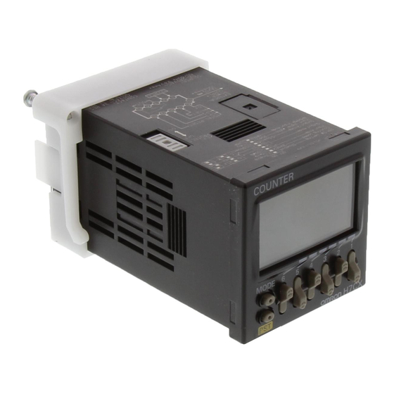
Multifunction Counter/Tachometer
H7CX Series
Please read and understand this catalog before purchasing the products. Please consult your OMRON representative if you have any questions
or comments. Refer to Warranty and Application Considerations (page 64), and Safety Precautions (page 59).
DIN 48
48 mm Multifunction Counter/Tachometer Series
• Highly visible display with backlit negative transmissive LCD.
• Intuitive setting enabled using ergonomic up/down digit keys (4-digit models) and DIP switch.
• PNP/NPN switchable DC voltage input.
• Finger-safe terminals (screw terminal block models).
• Complies with IP66/NEMA4/UL Type 4X (when using the Y92S-29 Waterproof Packing and Y92F-30 Flush Mounting Adapter).
H7CX-A
Multifunction Counter
Preset Counter
Total Counter
Batch Counter
Dual Counter
Tachometer
H7CX Series
Contents
Multifunction Counter
H7CX-A............................................................
Tachometer
H7CX-R............................................................ 42
Common to All Models
Safety Precautions ........................................... 59
Warranty and Application Consideration .......... 64
Multifunction Counter/Tachometer
H7CX-R
Tachometer
2
H7CX Series
1
Advertisement
Chapters
Table of Contents

Related Manuals for Omron H7CX - DATASHEET 2


Summary of Contents for Omron H7CX - DATASHEET 2
- Page 1 Multifunction Counter/Tachometer H7CX Series Please read and understand this catalog before purchasing the products. Please consult your OMRON representative if you have any questions or comments. Refer to Warranty and Application Considerations (page 64), and Safety Precautions (page 59). DIN 48 48 mm Multifunction Counter/Tachometer Series •...
-
Page 2: Table Of Contents
DIN 48 48 mm Multifunction Preset Counter with a Bright, Easy-to-view, Negative Transmissive LCD • Programmable PV color to visually alert when output status changes (screw terminal block models). • Configurable as 1-stage counter, 2-stage counter, total and pre- set counter, batch counter, dual counter, or tachometer. (Config- urability varies with model.) -
Page 3: Model Number Structure
Transistor output H7CX-ASD H7CX-A4SD H7CX-AWSD H7CX-A4WSD Note: Can be used as a 2-stage counter. In this case, each output can be flexibly allocated to either stage 1 or 2. Accessories (Order Separately) Name Models Flush Mounting Adapter (See note 1.) Y92F-30 Waterproof Packing (See note 1.) -
Page 4: Specifications
EEPROM (overwrites: 100,000 times min.) that can store data for 10 years min. Ambient temperature Operating: 10 to 55 C ( 10 to 50 C if counters are mounted side by side) (with no icing or condensation) Storage: 25 to 65 C (with no icing or condensation) - Page 5 EEPROM (overwrites: 100,000 times min.) that can store data for 10 years min. Ambient temperature Operating: 10 to 55 C ( 10 to 50 C if counters are mounted side by side) (with no icing or condensation) Storage: 25 to 65 C (with no icing or condensation)
- Page 6 2,000 VAC, 50/60 Hz for 1 min between current-carrying metal parts and non-current-carrying metal parts 2,000 VAC (for 100 to 240 VAC), 50/60 Hz for 1 min between power supply and input circuit (1,000 VAC for 24 VAC/ 12 to 24 VDC)
- Page 7 Load current (A) Reference: A current of 0.15 A max. can be switched at 125 VDC (cos =1) and current of 0.1 A max. can be switched if L/R=7 ms. In both cases, a life of 100,000 operations can be expected. The minimum applicable load is 10 mA at 5 VDC (failure level: P).
-
Page 8: Connections
Outputs take place according to designated output mode when corresponding preset is reached. Note: 1. In increment mode or increment/decrement mode, the present value returns to 0; in decrement mode, the present value returns to the set value with 1-stage models, and returns to set value 2 with 2-stage models. - Page 9 Terminal Arrangement Confirm that the power supply meets specifications before use. H7CX-A/-A4 H7CX-AD/-A4D 1-stage Contact Output 1-stage Contact Output Sensor, etc. Unused Unused Unused Unused Unused 12 VDC External power supply Note: Terminals 1 and 6 are connected internally. H7CX-AS/-A4S...
- Page 10 1 or 2 by setting in function selection mode. Input Circuits CP1, CP2, Reset/Reset 1, and Total Reset/Reset 2 Input +14 V Internal circuit Note: The circuit shown above is for no-voltage input (NPN input). H7CX-A Multifunction Preset Counter...
-
Page 11: Contact Input
Input Connections The inputs of the H7CX are no-voltage (short-circuit or open) inputs or voltage inputs. When using as a tachometer, CP2 input and total reset/reset 2 input are not available. No-voltage Inputs (NPN Inputs) Open Collector Voltage Output Contact Input... -
Page 12: Nomenclature
Nomenclature Indicators Operation Keys Reset Indicator (Orange) Mode Key Lit when the reset input (1) or reset key Used to switch mode and setting items. is ON. Reset Key The operation of the reset function Key Protection Indicator (Orange) depends on the configuration selected Control Output Indicator (Orange) as shown in the table below. -
Page 13: Dimensions
Dimensions Note: All units are in millimeters unless otherwise indicated. Counter (without Flush Mounting Adapter) Screw-terminal Models with External Power Supplies (Flush Mounting) H7CX-A H7CX-AW H7CX-AU H7CX-AS H7CX-AWS H7CX-AUD1 H7CX-A4 H7CX-A4W H7CX-AUSD1 H7CX-A4S H7CX-AWD1 H7CX-AWSD1 48 48 44.8 44.8 Note: M3.5 terminal screw (effective length: 6 mm) - Page 14 Y92S-29 (order separately) Panel Flush Mounting Adapter Waterproof Packing P3GA-11 (order separately) Back Connecting (51) Socket 98.7 Dimensions with Front Connecting Socket H7CX -A11@ 109.7 P2CF-11 Note: These dimensions vary with the kind of DIN track (reference value). H7CX-A Multifunction Preset Counter...
- Page 15 P3GA-11 Terminal Arrangement/ 27 dia. Internal Connections (Bottom View) 25.6 16.3 Note: Finger protection can be ensured by using in combination with the Y92A-48G Terminal Cover. Finger-safe Terminal Cover Conforming to VDE0106/P100 Y92A-48G Twelve, 6.4-dia. holes (Attachment for P3GA-11 Socket) 48 x 48 47.7 x 47.7...
- Page 16 2. The H7CX’s panel surface is water-resistive (conforming to IP66) and so even if drops of water penetrate the gaps be- tween the keys, there will be no adverse effect on internal circuits. If, however, there is a possibility of oil being present on the operator’s hands, use the Soft Cover.
-
Page 17: Operating Procedures
Output allocation Key protect level Note: 1. At the time of delivery, the H7CX is set to the 1-stage counter (2-stage counter for H7CX-AW@/-A4W@ models) configuration. 2. Set to output 2 time when using as a 2-stage counter or batch counter. -
Page 18: Operating Procedures (Counter Function)
For details, refer to page 36. Note: 1. Be sure to set pin 1 of the DIP switch to ON. If it is set to OFF, the DIP switch settings will not be enabled. 2. Changes to DIP switch settings are enabled when the power is turned ON. - Page 19 Settings for All Functions Note: At the time of delivery, the H7CX is set to the 1-stage counter (2-stage counter for H7CX-AW@/-A4W@ models) configuration. When using as a 2-stage (or 1-stage) counter, total and preset counter, batch counter, or dual counter, switch to the configuration using the procedure given on page 36.
- Page 20 25 pulses Set the way that control output for the present value is output. The possible settings are N, F, C, R, K-1, P, Q, A, K-2, D, L, and H. Output Encoder modes other than N, F, C, or K-1 cannot be set using the DIP switch and so use the operation keys if other modes are required.
- Page 21 When the key-protect switch is set to ON, it is possible to prevent setting errors by prohibiting the use of certain operation keys by specifying the key protect level (KP-1 to KP-5). The key protect indicator is lit while the key-protect switch is set to ON. Confirm the ON/OFF status of the key- protect switch after the H7CX is mounted to the panel.
- Page 22 (OUT1) turns ON. Dual Counter Dual Count Value Shows the sum of the CP1 present value and CP2 present value when the dual count calculating mode is ADD and shows the value obtained by Dual count value...
- Page 23 3. Counting starts when the CP1 is turned ON after turning ON the power. a must be greater than the minimum signal width. (See note 2.) 4. The meaning of the H and L symbols in the tables is ex- plained below. UP/DOWN B...
- Page 24 4. If reset/reset 1 is input while one-shot output is ON, one-shot output turns OFF. 5. If there is power failure while output is ON, output will turn ON again when the power supply has recovered. For one-shot output, output will turn ON again for the duration of the output time setting once the power supply has recovered.
- Page 25 4. If reset/reset 1 is input while one-shot output is ON, one-shot output turns OFF. 5. If there is power failure while output is ON, output will turn ON again when the power supply has recovered. For one-shot output, output will turn ON again for the duration of the output time setting once the power supply has recovered.
- Page 26 2. If reset/reset 1 is input while one-shot output is ON, one-shot output turns OFF. 3. If there is power failure while output is ON, output will turn ON again when the power supply has recovered. For one-shot output, output will turn ON again for the duration of the output time setting once the power supply has recovered.
- Page 27 4. Once batch input has been turned ON, it will return to the ON state after power interruptions. 5. If the batch count set value is changed from a value that is greater than the batch count value to one that is less, batch output will turn ON.
- Page 28 Dual Counter Operation Using the dual counter allows the count from 2 inputs to be added or subtracted and the result displayed. It is possible to specify a set value for which output turns ON when the set value matches the added or subtracted result.
- Page 29 2. Display flashes (1-second cycles). 3. Occurs when the present value or the total count value goes below 99,999 ( 999 with 4-digit models). 4. Occurs when the present value reaches 999,999 (9,999 with 4-digit models) under the following conditions: •...
-
Page 30: Operating Procedures (Tachometer Function)
For details, refer to page 36. Note: 1. Be sure to set pin 1 of the DIP switch to ON. If it is set to OFF, the DIP switch settings will not be enabled. 2. Changes to DIP switch settings are enabled when the power is turned ON. - Page 31 Settings for Advanced Functions Note: When using as a tachometer, switch to the tachometer configuration using the procedure given on page 36. Settings that cannot be performed with the DIP switch are performed with the operation keys. Note: 1. If the mode is switched to the function setting mode during operation, operation will Power ON continue.
- Page 32 Auto-zero Time (aut=) DIP switch.) It is possible to set the H7CX so that if there is no pulse for a certain time the display is force-set to 0. This time is called the auto-zero Set the output method for control output based on the OUT1/OUT2 time.
- Page 33 When the key-protect switch is set to ON, it is possible to prevent setting errors by prohibiting the use of certain operation keys by specifying the key protect level (KP-1 to KP-5). The key protect indicator is lit while the key-protect switch is set to ON. Confirm the ON/OFF status of the key- protect switch after the H7CX is mounted to the panel.
- Page 34 Reset to the factory settings using the (See note 1.) reset key. Note: 1. Includes the case where the EEPROM has reached its overwrite lifetime. 2. Occurs when the measurement value reaches 999,999. 3. Display flashes (1-second cycles). H7CX-A (Tachometer Function)
- Page 35 Measurement value limit (HI-LO) (Lower-limit) OUT1 set value OUT1 OUT2 ON condition for OUT1: measurement value OUT1 set value ON condition for OUT2: measurement value OUT2 set value Area OUT2 set value (AREA) Measurement value OUT1 set value...
-
Page 36: Operation In Configuration Selection Mode
Select which H7CX configuration is used (i.e., 1-stage counter, 2-stage counter, total and preset counter, batch counter, dual counter, or tachom- eter) in configuration selection mode. The H7CX is also equipped with a DIP switch monitor function, a convenient function that enables the settings of the DIP switch pins to be confirmed using the front display. -
Page 37: Additional Information
CP2 present value Note: 1. Perform settings using the keys ( key only with 6-digit models). 2. The above flowcharts outline the procedures for all models. For more details on each model, refer to page 19. H7CX-A Multifunction Preset Counter... - Page 38 OUT2 set value Prescale value Average processing Auto-zero time Startup time NPN/PNP input mode Display color Output allocation Key protect level Note: 1. All setting changes are performed using the key. 2. For details, refer to page 31. H7CX-A Multifunction Preset Counter...
- Page 39 Lists of Settings Fill in your set values in the set value column of the following tables and utilize the tables for quick reference. Configuration Selection Mode Parameter Parameter Setting range Default value Unit Set value name Configuration func 1cnt/2cnt/tcnt/bcnt/dcnt/taco (See note 1.)
- Page 40 Note: 1. The input mode is increment/decrement mode and the output mode is K-2, D, L, or H. 2. The dual count calculating mode is subtraction mode and the output mode is K-2, D, L, or H. Function Setting Mode...
- Page 41 Settings for Tachometer Operation Run Mode Parameter name Parameter Setting range Default value Unit Set value Measurement value 0 to 999999 Measurement Measurement 0 to 999999 value, OUT1 set value value OUT1 set value 0 to 999999 Measurement Measurement 0 to 999999...
-
Page 42: H7Cx-R
Transmissive LCD • Socket design allows either flush or surface mounting. • Operation in any of the four following modes is possible with the same Unit: Upper and lower limit, upper limit, lower limit, and ar- • Equipped with auto-zero time, average processing, and startup time functions. -
Page 43: Model Number Structure
50 cm (l) 7.3 mm (t) PFP-50N 1 m (l) 7.3 mm (t) PFP-100N 1 m (l) 16 mm (t) PFP-100N2 End Plate PFP-M Spacer PFP-S Note: Y92A-48G is a finger-safe terminal cover attached to the P3GA-11 Socket. H7CX-R Tachometer... -
Page 44: Specifications
Memory backup EEPROM (overwrites: 100,000 times min.) that can store data for 10 years min. Ambient temperature Operating: 10 to 55 C ( 10 to 50 C if tachometers are mounted side by side) (with no icing or conden- sation) Storage:... - Page 45 Load current (A) Reference: A current of 0.15 A max. can be switched at 125 VDC (cos =1) and current of 0.1 A max. can be switched if L/R=7 ms. In both cases, a life of 100,000 operations can be expected. The minimum applicable load is 10 mA at 5 VDC (failure level: P).
-
Page 46: Connections
12 VDC External power supply Note: 1. Terminals 4, 5, and 7 are all for the hold function. The func- tion is the same whichever terminal is connected. Terminals 4, 5, and 7 are not connected internally and so do not use them for bridge wiring. - Page 47 Input Connections The inputs of the H7CX-R can be used as either no-voltage (short-circuit or open) inputs or voltage inputs. They are set for use as voltage inputs at the time of delivery. No-voltage Inputs (NPN Inputs) Open Collector Voltage Output...
-
Page 48: Nomenclature
Indicators Operation Keys TACHOMETER Hold Indicator (Orange) Mode Key Lit when the hold input or hold key is Used to switch mode and setting items. Hold Key Key Protection Indicator (Orange) Used to sustain the measurement value Lit when the key protect switch is ON. -
Page 49: Dimensions
A = {48n 2.5 + (n 1) x 4} With Y92A-48 attached. A = (51n 5.5) 109.7 Note: These dimensions vary with the kind of DIN track (reference value). Accessories (Order Separately) Note: Refer to page 15 for details. H7CX-R... -
Page 50: Operating Procedures
Easy Confirmation of Switch Settings Using Indicators 8 times The ON/OFF status of the DIP switch pins can be confirmed using the front display. For details, refer to page 56. Note: 1. The characters displayed in reverse video are the default settings. - Page 51 Settings for Advanced Functions Settings that cannot be performed with the DIP switch are performed with the operation keys. Note: 1. If the mode is switched to the function setting mode during operation, operation will Power ON continue. 2. Changes made to settings in function setting mode are enabled for the first time when the mode is changed to run mode.
-
Page 52: Basic Functions
2 measurement values), 4 times, or 8 times. The measurement It is possible to set the H7CX-R so that if there is no pulse for a cer- cycle will be equal to the sampling cycle (200 ms) multiplied by the tain time the display is force-set to 0. - Page 53 Set the key protect level. When the key-protect switch is set to ON, it is possible to prevent setting errors by prohibiting the use of certain operation keys by specifying the key protect level (KP-1 to KP-5). The key protect level is set in the function setting mode. The key protect indicator is lit while the key-protect switch is set to ON.
- Page 54 Operation in Run Mode Set the values for each digit as required using the key. Output Mode: HI or LO Measurement Value Measurement value Displays the currently measured value. Comparison Value Measurement value Set comparison value. The measurement value is...
- Page 55 (LO) Measurement value Comparison value (Lower-limit) ON condition: Measurement value Comparison value Hold Function The measurement value (display value) and output are sustained while the hold input is ON. Example Output mode Operation setting Lower limit (LO) Hold input...
- Page 56 3. Display flashes (1-second cycles). Operation in DIP Switch Monitor Mode The H7CX-R is also equipped with a DIP switch monitor function, a convenient function that enables the settings of the DIP switch pins to be con- firmed using the front display.
-
Page 57: Additional Information
Prescale value Measurement value, Comparison value Auto-zero time Output Mode: HI-LO or AREA Startup time Measurement value Key protect level Measurement value, Comparison value 1 Measurement value, Comparison value 2 Note: All setting changes are performed using the key. H7CX-R Tachometer... - Page 58 Comparison value Comparison value 0 to 999999 Measurement value, Measurement value --- 0 to 999999 Comparison value 1 Comparison value 1 --- 0 to 999999 Measurement value, Measurement value --- 0 to 999999 Comparison value 2 Comparison value 2 ---...
-
Page 59: Safety Precautions
Safety Precautions (Common) Note: The following precautions are common for all H7CX models. • Leaving the H7CX with outputs ON at a high temperature for a long CAUTION time may hasten the degradation of internal parts (such as electrolytic capacitors). Therefore, use the product in combination Loose screws may occasionally result in fire or malfunction. -
Page 60: External Power Supply
Power supply voltage (VDC) Power Suppies • Turn the power ON and OFF using a relay with a rated capacity of 10 A minimum to prevent contact deterioration due to inrush current caused by turning the power ON and OFF. -
Page 61: Power Supplies
998.749 (= 999.999 1.25). • If the set value is set to a value greater than this, output will not turn Precautions for Correct Use Note: Output will turn ON, however, if a present value overflow occurs (FFFFFF or FFFF). - Page 62 Turning ON the Power using the Factory Settings When the power is turned ON using the factory settings, the output will turn ON after 999.9 s if no pulses are received as count input. Precautions for Correct Use Comparison Value Settings...
- Page 63 H7CX Series Safety Precautions...
-
Page 64: Warranty And Application Consideration
CONTRACT, WARRANTY, NEGLIGENCE, OR STRICT LIABILITY. In no event shall the responsibility of OMRON for any act exceed the individual price of the product on which liability is asserted. IN NO EVENT SHALL OMRON BE RESPONSIBLE FOR WARRANTY, REPAIR, OR OTHER CLAIMS REGARDING THE...
Need help?
Do you have a question about the H7CX - DATASHEET 2 and is the answer not in the manual?
Questions and answers