
Subscribe to Our Youtube Channel
Related Manuals for Unigas PG91


Summary of Contents for Unigas PG91
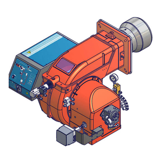
- Page 1 PG91 PG92 PG93 Progressive, Fully-modulating BurnersLight oil burners MANUAL OF INSTALLATION - USE - MAINTENANCE BURNERS - BRUCIATORI - BRULERS - BRENNER - QUEMADORES - ГОРЕЛКИ M039186CC Rev. 2.2 01/2013...
-
Page 2: Table Of Contents
TABLE OF CONTENTS WARNINGS ................................3 PART I: INSTALLATION ............................5 GENERAL FEATURES................................... 5 How to interpret the burner’s “Performance curve”.......................... 6 Technical specifications .................................. 7 Performance curves ..................................7 Overall dimensions ..................................8 MOUNTINGS AND CONNECTIONS .............................. 9 Packing ......................................9 Fitting the burner to the boiler ................................. - Page 3 DANGERS, WARNINGS AND NOTES OF CAUTION THIS MANUAL IS SUPPLIED AS AN INTEGRAL AND ESSENTIAL PART OF THE PRODUCT AND MUST BE DELIVERED TO THE USER. INFORMATION INCLUDED IN THIS SECTION ARE DEDICATED BOTH TO THE USER AND TO PERSONNEL FOLLOWING PRODUCT INSTALLATION AND MAINTENANCE.
- Page 4 3b) FIRING WITH GAS, LIGHT OIL OR OTHER FUELS DIRECTIVES AND STANDARDS Gas burners GENERAL European directives The burner shall be installed by qualified personnel and in compliance -Regulation 2016/426/UE (appliances burning gaseous fuels) with regulations and provisions in force; wrong installation can cause -2014/35/UE (Low Tension Directive) injuries to people and animals, or damage to property, for which the -2014/30/UE (Electromagnetic compatibility Directive)
-
Page 5: Warnings
Burner data plate Type Gas - Light oil burners For the following information, please refer to Model Year European Directives the data plate: S.Number -Regulation 2016/426/UE (appliances burning gaseous fuels) burner type and burner model: must be Output Oil Flow -2014/35/UE (Low Tension Directive) reported in any communication with the Fuel... -
Page 6: Part I: Installation
C.I.B. UNIGAS - M039186CC PART I: INSTALLATION GENERAL FEATURES The burners of this series represent monoblock burners made in die-cast aluminium housing with relative flange to work on heating generators. The output range is from 700kW to 4100kW (according to the model).They can be provided in progressive or fully-modula- ting version. -
Page 7: How To Interpret The Burner's "Performance Curve
C.I.B. UNIGAS - M039186CC How to interpret the burner’s “Performance curve” To check if the burner is suitable for the boiler to which it must be installled, the following parameters are needed: furnace input, in kW or kcal/h (kW = kcal/h / 860);... -
Page 8: Technical Specifications
C.I.B. UNIGAS - M039186CC Technical specifications BURNERS PG91 PG92 PG93 Output min. -max. kW 698 - 2093 849 - 2558 550 - 4100 Light oil rate min. -max. kg/h 59 - 176 72 - 215 46 - 345 Fuel Light oil Viscosity cSt @ 40 °C... -
Page 9: Overall Dimensions
Overall dimensions (mm) boiler recommended drilling template burner flange A(S*) A(L*) B(S*) B(L*) Omin Omax PG91 1259 1432 PG92 1253 1426 PG93 1256 1431 *S: standard blast tube *L: extended blast tube... -
Page 10: Mountings And Connections
C.I.B. UNIGAS - M039186CC MOUNTINGS AND CONNECTIONS Packing The burners are dispatched in wooden packages whose dimensions are:1730mm x 1280mm x 1020mm (L x P x H) Packing cases of this kind are affected by humidity and are not suitable for stacking. The fol- lowing are placed in each packing case. - Page 11 C.I.B. UNIGAS - M039186CC Fitting the burner to the boiler To install the burner into the boiler, proceed as follows: make a hole on the closing door of the combustion chamber as described on paragraph “Overall dimensions”) place the burner to the boiler: lift it up and handle it according to the procedure described on paragraph “Handling the burner”;...
-
Page 12: Hydraulic Diagrams For Light Oil Supplying Circuits
C.I.B. UNIGAS - M039186CC Hydraulic diagrams for light oil supplying circuits Fig. 3 - Gravity circuit Fig. 4 - Ring circuit Fig. 5 - Suction circuit Manual valve Light oil filter Light oil feeding pump One way valve Flexible hoses Relief valve NOTE: in plants where gravity or ring feed systems are provided, install an automatic interception device (see n. -
Page 13: Installation Diagram Of Light Oil Pipes
C.I.B. UNIGAS - M039186CC Installation diagram of light oil pipes PLEASE READ CAREFULLY THE “WARNINGS” CHAPTER AT THE BEGINNING OF THIS MANUAL. From tank To tank Fig. 6 - Double-pipe system The burner is supplied with filter and flexible hoses, all the parts upstream the filter and downstream the return flexible hose, must be installed by the customer. -
Page 14: Light Oil Pumps
C.I.B. UNIGAS - M039186CC Light oil pumps Suntec TA.. Oil viscosity 4 ÷ 450 cSt Oil temperature 0 ÷ 140°C Min. suction pressure - 0.45 bar to avoid gasing Max. suction pressure 5 bar Max. return pressure 5 bar Rotation speed 3600 rpm max. -
Page 15: Light Oil Circuit
C.I.B. UNIGAS - M039186CC Light oil circuit The fuel is pushed into the pump 1 to the nozzle 3 at the delivery pressure set by the pressure governor. The solenoid valve 2 set the fuel immission into the combustion chamber. The part of fuel that is not burnt goes back to the tank through the return circuit. The fuel amount to be burnt is adjusted by means of the burner actuator according to the adjustments set (see page 18). -
Page 16: Electrical Connections
C.I.B. UNIGAS - M039186CC Electrical connections RESPECT THE BASIC SAFETY RULES. MAKE SURE OF THE CONNECTION TO THE EARTHING SYSTEM. DO NOT REVERSE THE PHASE AND NEUTRAL CONNECTIONS. FIT A DIFFERENTIAL THERMAL MAGNET SWITCH ADE- QUATE FOR CONNECTION TO THE MAINS. STRICTLY OBSERVE THE DATA PLATE. -
Page 17: Light Oil Nozzles
Fig. 15 and Fig. 16, according to the burner type. Nozzles provided are the following according to the burner type. As far as reading the pressure values, see next paragraphs. PG91 - PG92: Bergonzo A3 (Fig. 16) PG93: Fluidics WR2 (Fig. 15) - Page 18 C.I.B. UNIGAS - M039186CC Fig. 16...
-
Page 19: Adjustments - Brief Description
C.I.B. UNIGAS - M039186CC Adjustments - brief description ATTENTION: before starting the burner up, be sure that the manual cutoff valves are open and check that the pres- sure upstream the gas train complies the value quoted on paragraph “Technical specifications”. Be sure that the mains switch is closed. - Page 20 C.I.B. UNIGAS - M039186CC be sure that the actuator cam for the “Startup enabling signal” (when used) is about 5° more than the ignition cam; start the burner up by means of the thermostat series and wait until the pre-purge time comes to an end;...
- Page 21 C.I.B. UNIGAS - M039186CC 11 To adjust the air flow rate in the high flame stage, loose the RA nut and screw VRA as to get the desired air flow rate: moving the rod TR towards the air damper shaft, the air damper opens and consequently the air flow rate increases, moving it far from the shaft the air damper closes and the air flow rate decreases.
-
Page 22: Adjustment By The Siemens Sql33.. Actuator
C.I.B. UNIGAS - M039186CC Adjustment by the Siemens SQL33.. actuator Check the fan-pump motor rotation and acting on its contactor CV (inside the control panel - see next picture): keep pressed for some seconds until the oil circuit is charged;CV CPbleed the air from the M pressure gauge port (Fig. - Page 23 C.I.B. UNIGAS - M039186CC manually drive the adjusting cam SV to the high flame position and set the actuator to the AUTO mode (by the related switch - see picture) to lock the adjusting cam. 10 the nozzle suplly pressureis already factory-set and must not be changed. Only if necessary, adjust the supply pressure as follows (see related paragraph);insert a pressure gauge into the port showed on Fig.
-
Page 24: Fully Modulating Burners
C.I.B. UNIGAS - M039186CC 15 to change the SV position set the actuator on the manual mode (MAN), turn the adjusting cam SV and set again the actuator to the AUTO mode to lock the adjusting cam; 16 act on the V screw that mathces the bearings referring to the adjusting cam position;... -
Page 25: Calibration Of Air Pressure Switch (When Provided)
C.I.B. UNIGAS - M039186CC Calibration of air pressure switch (when provided) To calibrate the air pressure switch, proceed as follows: Remove the transparent plastic cap. Once air and gas setting have been accomplished, startup the burner. During the pre-purge phase o the operation, turn slowly the adjusting ring nut VR in the clockwise direction until the burner lockout, then read the value on the pressure switch scale and set it to a value reduced by 15%. -
Page 26: Part Ii: Operation
C.I.B. UNIGAS - M039186CC PART II: OPERATION LIMITATIONS OF USE THE BURNER IS AN APPLIANCE DESIGNED AND CONSTRUCTED TO OPERATE ONLY AFTER BEING CORRECTLY CON- NECTED TO A HEAT GENERATOR (E.G. BOILER, HOT AIR GENERATOR, FURNACE, ETC.), ANY OTHER USE IS TO BE CONSI- DERED IMPROPER AND THEREFORE DANGEROUS. -
Page 27: Operation
C.I.B. UNIGAS - M039186CC OPERATION ATTENTION: before starting the burner up, be sure that the manual cutoff valves are open . Be usre that the mains switch is closed. Set to the ON position the switch A on the control panel of the burner. -
Page 28: Part Iii: Maintenance
C.I.B. UNIGAS - M039186CC PART III: MAINTENANCE At least once a year carry out the maintenance operations listed below. In the case of seasonal servicing, it is recommended to carry out the maintenance at the end of each heating season; in the case of continuous operation the maintenance is carried out every 6 months. -
Page 29: Removing The Combustion Head
C.I.B. UNIGAS - M039186CC Removing the combustion head Remove the top cover C; remove the photoresistor from its seat; unscrew the revolving connectors (E in figure) on the fuel pipes (use 2 spanners to avoid loosening the connections attached to the distributor block);... -
Page 30: Correct Position Of Electrodes And Nozzle
C.I.B. UNIGAS - M039186CC Correct position of electrodes and nozzle ATTENTION: avoid the electrodes to get in touch with metallic parts (blast tube, head, etc.), otherwise the boiler operation would be compromised. Check the electrodes position after any intervention on the combustion head. -
Page 31: Seasonal Stop
C.I.B. UNIGAS - M039186CC Checking the detection current To measure the detection signal follow the diagram in Fig. 25. If the signal is not in the advised range, check the electrical contacts, the cleaning of the combustion head, the position of the photore- sistor and if necessary replace it. -
Page 32: Troubleshooting
C.I.B. UNIGAS - M039186CC TROUBLESHOOTING MAIN SWITCH OPEN LINE FUSE INTERVENTION MAX. PRESSURE SWITCH FAULT FAN THERMAL CUTOUT INTERVENTION AUXILIARY RELAIS FUSES INTERVENTION CONTROL BOX FAULT ACTUATOR FAULT SMOKEY FLAME IGNITION TRANSFORMER FAULT IGNITION ELECTRODE DIRTY OR WRONG POSITIONED DIRTY NOZZLE... -
Page 33: Burner Exploded View
BURNER EXPLODED VIEW ITEM DESCRIPTION ITEM DESCRIPTION STANDARD BLAST TUBE 8.1.2 ACTUATOR 2.1.1 FRONT CONTROL PANEL 8.1.3 ACTUATOR SHAFT 2.1.2 LIGHT 8.1.4 BRACKET 2.1.3 LIGHT AIR INTAKE DAMPER 2.1.4 LOCK-OUT RESET BUTTON AIR INTAKE DAMPER 2.1.5 PROTECTION AIR INTAKE 2.1.6 SWITCH LOUVER SHAFT BOARD... - Page 35 SPARE PARTS Desription Code PG91 PG92 PG93 2020455 2020455 2020455 CONTROL BOX 2080206 2080206 2080206 IGNITION ELECTRODES 2090018 2090018 2090018 FUEL FILTER 2110048 2110048 2110048 GASKET 2150031 2150033 2150032 FAN WHEEL 2170302 2170302 2170302 IGNITION TRANSFORMER 2180276 2180277 2180206 ELECTRIC MOTOR...
-
Page 36: Electrical Wiring Diagrams
ELECTRIC WIRING DIAGRAMS ATTENTION: 1 - Electric supply 230V/400V 50Hz 3N a.c. 2 - Don't reverse phase and neutral 3 - Make sure that the burner is properly hearted Wiring diagram SE07-352 - Progressive Burners Wiring diagram SE07-401 - Fully-modulating Burners... -
Page 47: Appendix
APPENDIX The multicolour «LED» is the key indicating element for both visual diagnosis and interface diagnosis. SIEMENS OIL BURNERS AUTOMATIC CONTROLLER SIEMENS LMO14 - LMO24 - LMO44 The LMO... burner controls are designed for the start-up and supervision of single- or 2-stage forced draught oil burners in intermittent operation. Yellow-burning flames are supervised with photoresistive detectors Yellow QRB..., blue-burning flames with blue-flame detectors QRC... - Page 48 LMO24 - LMO44 Connection diagram and internal diagram LMO14 A ´ µC control µC2 µC1 t 3n t 3n t 3n 7130a01e/0700 7130d03e/ 0700 LMO24 - LMO44 Alarm device µC cont r ol µC 1 µC 2 kbr... Cable link (required only when no oil pre-heater is used) BV...
- Page 49 General unit data Mains voltage AC 230 V +10 % / -15 % AC 120 V +10 % / -15 % Mains frequency 50...60 Hz ±6 % External primary fuse (Si) 6.3A (slow) Power consumption 12 VA Mounting orientation optional Weight approx.
- Page 52 C.I.B. UNIGAS S.p.A. Via L.Galvani, 9 - 35011 Campodarsego (PD) - ITALY Tel. +39 049 9200944 - Fax +39 049 9200945/9201269 web site: www.cibunigas.it - e-mail: cibunigas@cibunigas.it Note: Specifications and and data subject to change. Errors and omissions excepted.
Need help?
Do you have a question about the PG91 and is the answer not in the manual?
Questions and answers