
Related Manuals for Unigas PG70


Summary of Contents for Unigas PG70
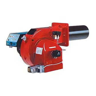
- Page 1 PG60 PG70 PG81 Progressive / Fully-modulating Light oil burners MANUAL OF INSTALLATION - USE - MAINTENANCE BURNERS - BRUCIATORI - BRULERS - BRENNER - QUEMADORES - ГОРЕЛКИ M039191CA Rel: 0.1 09/2011...
-
Page 2: Table Of Contents
ROUTINE MAINTENANCE ................................28 Light oil filter maintenance ................................28 Removing the combustion head and the oil gun ........................... 29 Removing the oil gun (PG70-PG81) ............................. 29 Correct position of electrodes and combustion head ........................30 Replacing the ignition electrodes ..............................30 Cleaning and replacing the detection photocell ........................... -
Page 3: Warnings
WARNINGS THIS MANUAL IS SUPPLIED AS AN INTEGRAL AND ESSENTIAL PART OF THE PRODUCT AND MUST BE DELIVERED TO THE USER. INFORMATION INCLUDED IN THIS SECTION ARE DEDICATED BOTH TO THE USER AND TO PERSONNEL FOLLOWING PRO- DUCT INSTALLATION AND MAINTENANCE. THE USER WILL FIND FURTHER INFORMATION ABOUT OPERATING AND USE RESTRICTIONS, IN THE SECOND SECTION OF THIS MANUAL. - Page 4 DIRECTIVES AND STANDARDS 3b) FIRING WITH GAS, LIGHT OIL OR OTHER FUELS Gas burners GENERAL European directives: The burner shall be installed by qualified personnel and in com- - Directive 90/396/CEE - Gas Appliances; pliance with regulations and provisions in force; wrong installation Directive 2006/95/EC on low voltage;...
-
Page 5: Part I: Installation
CIB UNIGAS - M039191CA PART I: INSTALLATION GENERAL FEATURES Monobloc burners of this series are made in die-cast aluminium housing with relative flange to work on heating generators. The output range is from 150kW to 1900kW (according to the model). -
Page 6: Technical Specifications
CIB UNIGAS - M039191CA Technical specifications BURNERS PG60 PG70 PG81 Output min. -max. kW 151 - 791 291 - 1047 264-1900 Light oil rate min. -max. kg/h 13 - 67 25 - 88 22-160 Fuel Light oil Viscosity 1.3 °E @20°C... -
Page 7: Overall Dimensions
OVERALL DIMENSIONS (mm) boiler drilling plate 1004 1202 PG60 1035 1185 PG70 1165 1315 PG81... -
Page 8: Mountings And Connections
The burners are dispatched in wooden pakages whose dimensions are: PG60: 1200 x 670 x 540 mm PG70-PG81: 1280 x 850 x 760 mm Packing cases of this kind are affected by humidity and are not suitable for stacking. The following are placed in each packing case. -
Page 9: Hydraulic Diagrams For Light Oil Supplying Circuits
CIB UNIGAS - M039191CA Hydraulic diagrams for light oil supplying circuits Fig. 2 - Gravity circuit Fig. 3 - Ring circuit Fig. 4 - Suction circuit Manual valve Light oil filter Light oil feeding pump One way valve Flexible hoses Relief valve NOTE: in plants where gravity or ring feed systems are provided, install an automatic interception device (see n. -
Page 10: Installation Diagram Of Light Oil Pipes
CIB UNIGAS - M039191CA Installation diagram of light oil pipes PLEASE READ CAREFULLY THE “WARNINGS” CHAPTER AT THE BEGINNING OF THIS MANUAL. From tank To tank Fig. 5 - Double-pipe system The burner is supplied with filter and flexible hoses, all the parts upstream the filter must be installed by the customer. As far as the hoses connection, see the related paragraph.. -
Page 11: About The Use Of Fuel Pumps
CIB UNIGAS - M039191CA Suntec TA Danfoss KSM..L Bleed Bleeding in two-pipe operation is automatic : i t is assured by a bleed flat on the piston. In one-pipe operation, the p lug of a pressure gauge port must be loosened until the air is evacuated from the system. -
Page 12: Light Oil Pumps
CIB UNIGAS - M039191CA Light oil pumps The pumps provided with these burners can be: PG60: Suntec AJ6 PG70: Suntec J6/Danfoss RSB30 PG81: Suntec TA2 / Danfoss KSM50 PumpSuntec AJ6 Viscosity 2.8 - 75 cSt Oil temperature 60°C max Inlet maximum pressure... -
Page 13: Connecting The Light Oil Flexible Hoses
CIB UNIGAS - M039191CA Suntec TA.. Oil viscosity 4 - 450 cSt Oil temperature 0 - 140°C Min. suction pressure - 0.45 barto avoid gasing Max. suction pressure 5 bar Max. return pressure 5 bar Rotation speed 3600 rpm max. -
Page 14: Light Oil Circuit
CIB UNIGAS - M039191CA Light oil circuit The fuel is pushed into the pump 1 to the nozzle 3 at the delivery pressure set by the pressure governor. The solenoid valve 2 set the fuel immission into the combustion chamber. The part of fuel that is not burnt goes back to the tank through the return circuit. The fuel amount to be burnt is adjusted by means of the burner actuator according to the adjustments set (see pag. -
Page 15: Light Oil Nozzles
CIB UNIGAS - M039191CA Light oil nozzles The light oil fl ow rate can be adjusted choosing a by-pass nozzle that suits the boiler/utilisation’s output and setting the delivery and return pressure values according to the values quoted on diagram on Fig. 9. -
Page 16: Electrical Connections
CIB UNIGAS - M039191CA Electrical connections RESPECT THE BASIC SAFETY RULES. MAKE SURE OF THE CONNECTION TO THE EARTHING SYSTEM. DO NOT REVERSE THE PHASE AND NEUTRAL CONNECTIONS. FIT A DIFFERENTIAL THERMAL MAGNET SWITCH ADE- QUATE FOR CONNECTION TO THE MAINS. STRICTLY OBSERVE THE DATA PLATE. -
Page 17: Adjustments
Adjustment procedure To change the burner setting during the testing in the plant, follow the next procedure, according to the actuator model provided (mod. Berger STM30.. or mod. Siemens SQL..). PG60: Berger STA12.. PG70-PG81: Berger STM30.. / Siemens SQL33.. -
Page 18: Adjustment By The Berger Stm30
CIB UNIGAS - M039191CA Adjustment by the Berger ST.. actuator Open the electrical panel to check the motor rotation and act directly on its solenoi starter (see next picture): keep pressed until the oil circuit is charged. bleed the air from the M pressure gauge port (Fig. 14) by loosing the cap without removing it, then release the solenoid starter. - Page 19 CIB UNIGAS - M039191CA values and eventually adjusting the oil pressure (see next step). STA12.. Actuator cams ST2 High flame ST0 Stand-by and Ignition ST1 Low flame MV Startup signal STM30.. Actuator cams MAN-AUTO High flame Stand-by and Ignition Low flame Startup signal the nozzle supply pressure is already factory-set and must not be changed.
- Page 20 CIB UNIGAS - M039191CA 10 in order to get the maximum oil flow rate, adjust the pressure (reading its value on the PG pressure gauge) without changing th e air flow rate set during the gas operation adjustments (see prevoius paragraph): checking always the combustion parameters, the adjustment is to be performed by means of the SV adjusting cam screw (see picture Fig.
-
Page 21: Adjustment By The Siemens Sql33.. Servocontrol
CIB UNIGAS - M039191CA 15 set the TAB thermostat to the minimum in order that the actuator moves progressively towards the low flame position; 16 move cam III (low flame) towards the minimum to move the actuator towards the low flame until the two bearings find the adjusting screw that refers to a lower position: screw V to increase the rate, unscrew to decrease, in order to get the pressure as showed on diagram in Fig. - Page 22 CIB UNIGAS - M039191CA Turn the burner on by means of its main switch A: if the burner locks (LED B on in the control panel) press the RESET button (C) on the control panel (see next picture) - see chapter “OPERATION” on page 26.
- Page 23 CIB UNIGAS - M039191CA Pressure gauge port Fig. 19 - Light oil manifold (PG60) Pressure gauge port Fig. 20 - Combustion head with light oil gun (PG70 - PG81) Fig. 21 11 in order to get the maximum oil flow rate, adjust the pressure (reading its value on the PG pressure gauge) without changing th e air flow rate set during the gas operation adjustments (see prevoius paragraph): checking always the combustion parameters, the adjustment is to be performed by means of the SV adjusting cam screw (see picture Fig.
- Page 24 CIB UNIGAS - M039191CA PG60: To let the burner operate at a lower output, turn clockwise the VRT screw and move progressively the combustion head back towards the MIN position. PG70-PG81: To let the burner operate at a lower output, loose the VB screw and move progressively the combustion head back towards the MIN position, by turning clockwise the VRT ring nut.
-
Page 25: Fully Modulating Burners
CIB UNIGAS - M039191CA 22 The low flame position must never match the ignition position that is why cam BF must be set 20°- 30° more than the ignition posi- tion. NOTE: to change the low flame position, act exclusively on the actuator cam. -
Page 26: Part Ii: Operation
CIB UNIGAS - M039191CA PART II: OPERATION LIMITATIONS OF USE THE BURNER IS AN APPLIANCE DESIGNED AND CONSTRUCTED TO OPERATE ONLY AFTER BEING CORRECTLY CON- NECTED TO A HEAT GENERATOR (E.G. BOILER, HOT AIR GENERATOR, FURNACE, ETC.), ANY OTHER USE IS TO BE CONSI- DERED IMPROPER AND THEREFORE DANGEROUS. -
Page 27: Burner Control Panel
CIB UNIGAS - M039191CA Burner control panel PG60 Fig. 22 PG70-PG81 Fig. 23 Keys ON-OFF main switch Lockout signalling lamp Conreol box release pushbutton Signalling lamp for light oil solenoid valve opening Thermal cutout intervention signalling lamp High flame operation signalling lamp... -
Page 28: Part Iii: Maintenance
CIB UNIGAS - M039191CA PART III: MAINTENANCE At least once a year carry o ut the maintenance operations listed below. In the case of seasonal servicing, it is re commended to carry out the main tenance at the e nd of each heating season; in the case of continuous operation the maintenance is carried out every 6 months. -
Page 29: Removing The Combustion Head And The Oil Gun
CIB UNIGAS - M039191CA Removing the combustion head and the oil gun Remove the top cover C; remove the photoresistor from its seat; unscrew the revolving connectors (E in figure) on the fuel pipes (use 2 spanners to avoid loosening the connections attached to the distributor block);... -
Page 30: Correct Position Of Electrodes And Combustion Head
CIB UNIGAS - M039191CA Correct position of electrodes and combustion head ATTENTION: avoid the ignition electrodes to get in touch with metallic parts (blast tube, head, etc.), otherwise the boiler’s operation would be compromised. Check the electrodes position after any intervention on the combustion head. -
Page 31: Checking The Detection Current
CIB UNIGAS - M039191CA Checking the detection current To measure the detection signal follow the diagram on the next picture. If the signal is not in the advised range, check the electrical contacts, the cleaning of the combustion head, the position of the photore- sistor and if necessary replace it. -
Page 32: Electrical Wiring Diagrams
PG60 G-.PR... - Page 36 PG60 G-.MD...
- Page 41 PG70 - PG81 G-.PR...
- Page 45 PG70 - PG81 G-.MD...
- Page 50 CIB UNIGAS - M039191CA SPARE PARTS Desription Code Quantity PG60 PG70 PG81 LOA24: 2020445 LOA44: 2020412 LOA44: 2020412 CONTROL BOX LMO24: 2020453 LMO44: 2020455 LMO44: 2020455 2080205 2080206 2080206 IGNITION ELECTRODES 2090016 2090025 2090018 FUEL FILTER 2110013 2110033 2110033 GASKET...
-
Page 51: Appendix
CIB UNIGAS - M039191CA APPENDIX Operation Lock-out reset button «EK...» is the key operatin g element for SIEMENS OIL BURNERS AUTOMATIC CONTROLLER LMO24 - resetting the burn er control and fo r activating / deactivating t he LMO44 diagnostic functions. - Page 52 CIB UNIGAS - M039191CA Oil pre-heater During the time the cause of fault is diagnosed, the control outputs are QRB Photoresistive detector deactivated. QRC Blue-flame detector Burner remains shut down bl = blue Fault status signal «AL» at terminal 10 is activated...
Need help?
Do you have a question about the PG70 and is the answer not in the manual?
Questions and answers