
Related Manuals for Unigas P75A


Summary of Contents for Unigas P75A
- Page 1 P75A - P75R R75A - R75R RX75 - RX75S - RX75R GAS BURNERS MANUAL OF INSTALLATION - USE - MAINTENANCE BURNERS - BRUCIATORI - BRULERS - BRENNER - QUEMADORES - ГОРЕЛКИ M039277CF Rel 0.0 10/2019...
-
Page 2: General Introduction
DANGERS, WARNINGS AND NOTES OF CAUTION THIS MANUAL IS SUPPLIED AS AN INTEGRAL AND ESSENTIAL PART OF THE PRODUCT AND MUST BE DELIVERED TO THE USER. INFORMATION INCLUDED IN THIS SECTION ARE DEDICATED BOTH TO THE USER AND TO PERSONNEL FOLLOWING PRODUCT INSTALLATION AND MAINTENANCE. -
Page 3: Directives And Standards
3b) FIRING WITH GAS, LIGHT OIL OR OTHER FUELS DIRECTIVES AND STANDARDS Gas burners GENERAL European directives The burner shall be installed by qualified personnel and in compliance -Regulation 2016/426/UE (appliances burning gaseous fuels) with regulations and provisions in force; wrong installation can cause -2014/35/UE (Low Tension Directive) injuries to people and animals, or damage to property, for which the -2014/30/UE (Electromagnetic compatibility Directive) -
Page 4: Symbols Used
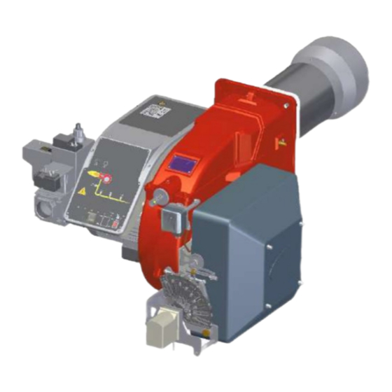
Burner data plate Type Gas - Light oil burners For the following information, please refer to Model Year European Directives the data plate: S.Number -Regulation 2016/426/UE (appliances burning gaseous fuels) burner type and burner model: must be Output Oil Flow -2014/35/UE (Low Tension Directive) reported in any communication with the Fuel... - Page 5 PART I: SPECIFICATIONS PART I: SPECIFICATIONS BURNERS FEATURES RX75, RX75S, R75R, R75A, R75R P75A ,P75R Note: the figure is indicative only. Control panel with startup switch Gas valves group Electrical panel Air intake Blast tube + Combustion head Flange Adjusting cam (progressive/fully modulating burners only) Air pressure switch Gas operation: the gas coming from the supply line, passes through the valves group provided with filter and stabiliser.
-
Page 6: Burner Model Identification
Burners are identified by burner type and model. Burner model identification is described as follows. Type RX75R Model MD. S. BURNER TYPE RX75 - RX75S - RX75R - R75A - R75R - P75A - P75R FUEL M - Natural gas L - LPG B - Biogas C - Town gas... -
Page 7: Technical Specifications
PART I: SPECIFICATIONS Technical Specifications BURNER TYPE RX75S M-.. RX75R M-.. RX75 M-.. 300 - 1150 290 - 1400 350 - 1800 Output min. - max. kW Natural gas Fuel Category (see next paragraph) 32 - 122 31 - 148 37 - 190 Gas flow rate min.-max. - Page 8 PART I: SPECIFICATIONS BURNER TYPE P75R M-.. P75A M-.. P75A L-.. 320 - 2050 320 - 2050 320 - 1650 Output min. - max. kW Natural gas Natural gas Fuel Category (see next paragraph) 3B/P 34 - 175 34 - 217...
- Page 9 Overall dimensions (mm) O min. O max. Boiler recommended drilling template and burner flange DN (*) V(**) 1267 1352 372 305 390 928 352 1078 716 362 219 249 233 300 453 233 457 130 327 541 608 210 155 1267 1352 372 305 390 928 352...
- Page 10 1326 1050 P75R PR/MD - 1.65 1216 1326 1134 P75R PR/MD - 1.80 1216 1326 1108 P75A PR/MD - 1.50 1334 1050 P75A PR/MD - 1.65 1334 1134 P75A PR/MD - 1.80 1334 1108 BS = standard blast tube BL = long blast tube DN = gas valves size (**) According to the gas train size and the burner type, MB-DLE or VGD valves are supplied.
- Page 11 O min. O max. Boiler recommended drilling template and burner flange TIPO DN(*) V(**) 1313 1423 372 385 495 928 350 1078 716 362 234 264 233 300 420 233 457 130 327 541 575 210 155 1313 1423 372 385 495 928 350 1013 651 362 234 264 233 300 420 233 472 130 342 526...
- Page 12 PART I: SPECIFICATIONS How to read the burner “Performance curve” To check if the burner is suitable for the boiler to which it must be instal- Campo di lavoro bruciatori lled, the following parameters are needed: Tipo P60 Mod. M-xx.x.IT.A.0.50 - M-.xx.x.IT.A.0.65 furnace input, in kW or kcal/h (kW = kcal/h/860);...
-
Page 13: Performance Curves
RX75R RX75 R75R / P75R R75A / P75A To get the input in kcal/h, multiply value in kW by 860. Data are referred to standard conditions: atmospheric pressure at 1013mbar, ambient temperature at 15° C NOTE: The performance curve is a diagram that represents the burner performance in the type approval phase or in the laboratory tests, but does not represent the regulation range of the machine. - Page 14 Gas rate Stm RX75 Gas rate Stm R75R / P75R R75A / P75A Gas rate Stm Gas rate Stm ATTENTION: the gas rate value is quoted on the x-axis, the related network pressure is quoted on the y-axis (pressure value in the combustion chamber is not included). To know the minimum pressure at the gas train inlet, necessary to get the requested gas rate, add the pressure value in the combustion chamber to the value read on the y-axis.
- Page 15 PART I: SPECIFICATIONS Pressure in the Network / gas flow rate curves(LPG) R75A L-.. / P75A L-.. Gas rate Stm ATTENTION: the gas rate value is quoted on the x-axis, the related network pressure is quoted on the y-axis (pressure value in the combustion chamber is not included). To know the minimum pressure at the gas train inlet, necessary to get the requested gas rate, add the pressure value in the combustion chamber to the value read on the y-axis.
- Page 16 THE USER CAN REFERS TO THE PRESSURE-RATE CURVES AS GENERAL INFORMATION ONLY. Pressure - rate in combustion head curves (natural gas) Curves are referred to pressure = 0 mbar in the combustion chamber! RX75S M-.. RX75R M-.. RX75 M-.. R75R M-.. / P75R M-.. R75A M-.. / P75A M-..
- Page 17 PART I: SPECIFICATIONS Pressure - rate in combustion head curves (LPG) Curves are referred to pressure = 0mbar in the combustion chamber! R75A L-.. / P75A L..
- Page 18 PART II: INSTALLATION PART II: INSTALLATION MOUNTING AND CONNECTING THE BURNER Transport and storage ATTENTION! The equipment must be installed in compliance with the regulations in force, following the manufac- turer’s instructions, by qualified personnel. All handling operations must be carried out with appropriate resources and qualified personnel ATTENTION: Use intact and correctly dimensioned hoisting equipment, conforms to the local regulations and health and safety regulations.
- Page 19 SIDE DOWN Matching the burner to the boiler (R75R - R75A - P75R - P75A) The burners described in this manual have been tested with combustion chambers that comply with EN676 regulation and whose dimensions are described in the diagram . In case the burner must be coupled with boilers with a combustion chamber smaller in diameter or shorter than those described in the diagram, please contact the supplier, to verify that a correct matching is possible, with respect of the application involved.
- Page 20 PART II: INSTALLATION Matching the burner to the boiler low NOx burners) (RX75 - RX75S - RX75R) The burners described in this manual have been tested with combustion chambers that comply with EN676 regulation and whose dimensions are described in the diagram . In case the burner must be coupled with boilers with a combustion chamber smaller in dia- meter or shorter than those described in the diagram, please contact the supplier, to verify that a correct matching is possible, with respect of the application involved.
- Page 21 PART II: INSTALLATION GAS TRAIN CONNECTIONS The diagrams show the components of the gas trai included in the delivery and which must be fitted by the installer.The diagrams are in compliance with the current laws. Gas train with valves group MB-DLE (2 valves + gas filter + pressure governor) BY OTHERS BY BURNER CONSTRUCTOR GAS INLET...
-
Page 22: Assembling The Gas Train
PART II: INSTALLATION MultiBloc MB-DLE - Assembling the gas train F”direction” arrows for gas supply network installation Keys 1 Gasket 2 Gas filter 3 Gas valves group 4 Bellows unit 41Manual valve MULTIBLOC DUNGS MB-DLE 405..412 Mounting 1. Mount flange onto tube lines: use appropriate sealing agent (see Fig. 9); 2. - Page 23 PART II: INSTALLATION MultiBloc MBE Actuator VD-V Actuator VD-R Gas filter PS pressure Pressure switch PG min sensor Leakage pressure switch Valve body VB Pressure switch PG max Fig. 15Example of gas train MBE To mount the gas train, proceed as follows: 1-a) in case of threaded joints: use proper seals according to the gas used;...
- Page 24 PART II: INSTALLATION Mounting VD-R & PS-... Actuator VD-R Actuator VD-V 1. Gas pressure regulation is possible with VD-R and PS pressure sensor only. WARNING!!!!. For US/CN installation, the output pressure must be monitoried by min. and max. pressure switches set to +/- 20% of the setpoint. 2.
- Page 25 PART II: INSTALLATION Siemens VGD20.. e VGD40.. Siemens VGD20.. and VGD40.. gas valves - with SKP2.. (pressure governor) - Connect the reference gas pipe (TP in figure; 8mm-external size pipe supplied loose), to the gas pressure nipples placed on the gas pipe, downstream the gas valves: gas pressure must be measured at a distance that must be at least 5 times the pipe size.
- Page 26 PART II: INSTALLATION Once the train is installed, connect the gas valves group and pressure switches plugs. Gas Filter (if provided) The gas filters remove the dust particles that are present in the gas, and prevent the elements at risk (e.g.: burner valves, counters and regulators) from becoming rapidly blocked.
-
Page 27: Electrical Connections
PART II: INSTALLATION ELECTRICAL CONNECTIONS WARNING! Respect the basic safety rules. make sure of the connection to the earthing system. do not reverse the phase and neutral connections. fit a differential thermal magnet switch adequate for connection to the mains. WARNING! before executing the electrical connections, pay attention to turn the plant’s switch to OFF and be sure that the burner’s main switch is in 0 position (OFF) too. -
Page 28: Limitations Of Use
PART III: OPERATION PART III: OPERATION LIMITATIONS OF USE THE BURNER IS AN APPLIANCE DESIGNED AND CONSTRUCTED TO OPERATE ONLY AFTER BEING CORRECTLY CONNEC- TED TO A HEAT GENERATOR (E.G. BOILER, HOT AIR GENERATOR, FURNACE, ETC.), ANY OTHER USE IS TO BE CONSIDE- RED IMPROPER AND THEREFORE DANGEROUS. - Page 29 PART III: OPERATION Fig. 20 - Burner front panel Keys Lock-out LED Hi-flame operation LED Lo-flame operation LED “Ignition transformer operation” LED “Fan motor overload tripped” LED “EV2 opening” LED “EV1 opening” LED “Gas pressure switch signal ” LED Gas proving system lockout signalling LED Main switch Reset pushbutton for control box Operation selector MAN - AUTO (operation in manual...
-
Page 30: Pressure Taps
PART III: OPERATION MultiBloc MBE Regulation VD-R whith PS Setting scale is „Not“ linear! Various sensors available. Output pressure according to sensor‘s measuring range. Increasing pressure Adjust the outlet pressure to the value specified by the burner or equipment manufacturer! Decreasing pressure While making outlet pressure adjustments, do not exceed a value that creates a hazardous condition to the... - Page 31 PART III: OPERATION Adjusting the gas valves group Multibloc MB-DLE VS T(VR) The multibloc unit is a compact unit consisting of two valves, gas pressure switch, pres- sure stabilizer and gas filter. The valve is adjusted by means of the RP regulator after slackening the locking screw VB by a number of turns.
- Page 32 Adjusting the combustion head CAUTION: perform these adjustments once the burner is turned off and cooled. R75A, R75R, P75A, P75R The burner is factory-adjusted with the combustion head in the "MAX" position, accordingly to the maximum power. To operate the bur- ner at a lower power, progressively shift back the combustion head, towards the "MIN"...
- Page 33 PART III: OPERATION (R75A M-..) Center head holes gas flow regulation To adjust the gas flow, partially close the holes, as follows: loosen the three V screws that fix the adjusting plate D; insert a screwdriver on the adjusting plate notches and let it move CW/CCW as to open/close the holes; once the adjustmet is performed, fasten the V screws.
- Page 34 PART III: OPERATION Adjusting the gas valves group and removing the filter MULTIBLOC DUNGS MB-DLE 405..412 Check the filter at least once a year! Change the filter if the pressure difference between pressure connection 1 and 3 (Fig. 28-Fig. 29)is p > 10 ...
- Page 35 PART III: OPERATION MultiBloc MBE MultiBloc VD Mounting to push position 1. Position VD on VB, fig. 2+3. 2. Slide VD forward up to the stop, fig. 4. 3. Screw VD on with 2 M5 screws for each, max. 5 Nm/44 in.-lb., fig. 5/6. 4.
-
Page 36: Adjustment Procedure
PART III: OPERATION Adjustment procedure Turn the burner on by means of its main switch S1: if the burner locks (LED B1 on in the control panel) press the RESET button (S2) on the control panel. See chapter “Operation” for further details. check the fan motor rotation Start the burner up by means of the thermostat series and wait unitl the pre-purge phase comes to end and that burner starts up;... - Page 37 PART III: OPERATION Double-stage burners drive the burner to the low flame stage by means of the TAB thermostat; 10 ;In order to change the gas flow rate slacken the nuts DB (Fig. 27) and adjust the opening angle of the gas butterfly valve by rota- ting the rod TG (clockwise rotation increases gas flow, anticlockwise rotation decreases it).
- Page 38 PART III: OPERATION Progressive burners Once the procedure till step 8 described on paragraph “” on page 30, is accomplished, go on as follows: set the low flame cam matching the high flame cam; 10 set the TAB thermostat to the minimum in order that the actuator moves progressively towards the low flame position;; The manual air damper control is not provided on these actuators.
- Page 39 PART III: OPERATION Calibration air and gas pressure switches The air pressure switch locks the control box if the air pressure is not the one requested. If it happens, unlock the burner by means of the control box unlock pushbutton, placed on the bur- ner control panel.
-
Page 40: Routine Maintenance
PART IV: MAINTENANCE PART IV: MAINTENANCE At least once a year carry out the maintenance operations listed below. In the case of seasonal servicing, it is recommended to carry out the maintenance at the end of each heating season; in the case of continuous operation the maintenance is carried out every 6 months. - Page 41 PART IV: MAINTENANCE Adjusting the gas valves group and removing the filter MULTIBLOC DUNGS MB-DLE 405..412 Check the filter at least once a year! Change the filter if the pressure difference between pressure connection 1 and 3 (Fig. 1-Fig. 3)is p > 10 ...
- Page 42 PART IV: MAINTENANCE MultiBloc MBE MultiBloc VD Mounting to push position 1. Position VD on VB, fig. 2+3. 2. Slide VD forward up to the stop, fig. 4. 3. Screw VD on with 2 M5 screws for each, max. 5 Nm/44 in.-lb., fig. 5/6. 4.
- Page 43 G hole. RX75S 3÷4 the gap between ignition electrode EA and grounded electrode M must be 3 ÷ 4 mm. Ignition electrod must be positioned over the G hole. ER - Detection electrode EA - Ignition electrode R75A, P75A...
-
Page 44: Replacing The Electrodes
Reassemble the burner by fllowing the procedure in the reversed order. Detection electrode RX75, RX75S, RX75R R75A . P75A Detection electrode R75R, P75R WIRING DIAGRAMS Refer to the attached wiring diagrams. -
Page 45: Seasonal Stop
PART IV: MAINTENANCE Checking the detection current with electrode (natural gas) To check the detection signal follow the scheme in the picture below. If the signal is less than the value indicated, check the position of the detection electrode or detector, the electrical contacts and, if necessary, replace the electrode or the detector. Connector LME: 1 LGK: 24... - Page 46 PART IV: MAINTENANCE TROUBLESHOOTNG GUIDE - Gas operation * No electric power supply * Wait until power supply is back * Main switch open * Close the switch * Thermostats open * Check set points and thermostat connections * Bad thermostat set point or broken thermostat * Set or replace the thermostat * No gas pressure * Restore gas pressure...
- Page 47 BURNER EXPLODED VIEW - R75A, R75R 11.2 11.2.1 11.2.2 6.5.2 6.5.1 11.4...
- Page 48 BOARD IGNITION CABLE 1.1.1 BOARD GAS MANIFOLD 1.1.2 CONTROL BOX SOCKET DETECTION ELECTRODE 1.1.3 IGNITION TRANSFORMER STANDARD COMBUSTION HEAD 1.1.4 PRINTED CIRCUIT BOARD O RING 1.1.5.1 FRONT CONTROL PANEL 6.5.1 NOZZLE HOLDER 1.1.5.2 LIGHT 6.5.2 IGNITION ELECTRODE 1.1.5.3 LIGHT AIR INTAKE 1.1.5.4 FLAME UNLOCK BUTTON AIR PRESSURE SWITCH...
-
Page 49: Start-Up Program
APPENDIX SIEMENS LME11/21/22 CONTROL BOX The series of equipment LME.. is used for the starup and supervisione of 1- or 2- stage gas burners. The series LME.. is interchangeable with the series LGB.. and LMG.., all diagrams and accessories are interchangea- START-UP PROGRAM ble. - Page 50 LME11 control sequence LME21 control sequence B´ B´ SB / R SB / R W / GP W / GP (LR) BV2 7101d05/0206 Control sequence Waiting time LME22 control sequence Purge time B´ TSA Ignition safety time SB / R Preignition time W / GP Postignition time...
- Page 51 LME11 connection diagram Connection diagram Error message (alarm) Fuel valve PC control EK2 Remote lockout reset button RESET Flame signal Gas pressure switch Air pressure switch Load controller K2/1 K2/2 Fan motor Control thermostat/pressurestat Safety limit thermostat R / W Limit thermostat /pressure switch Ignition transformer 7101 24 /0606...
- Page 52 CONTROL PROGRAM IN THE EVENT OF FAULT CONTROL BOX LOCKED If a fault occurs, all outputs will immediately be deactivated (in less In the event of lockout, the LME.. remains locked and the red signal lamp than 1s). (LED) will light up.The burner control can immediately be reset. This state After an interruption of power, a restart will be made with the full pro- is also mantained in the case fo mains failure.
- Page 56 C.I.B. UNIGAS S.p.A. Via L.Galvani, 9 - 35011 Campodarsego (PD) - ITALY Tel. +39 049 9200944 - Fax +39 049 9200945/9201269 web site: www.cibunigas.it - e-mail: cibunigas@cibunigas.it Note: specifications and data subject to change. Errors and omissions excepted.
- Page 57 MANUAL FOR OPERATION AND CALIBRATION MODULATOR SIEMENS RWF 40…. M12905CH Rev. 07 11/09...
-
Page 58: Instrument Mounting
INSTRUMENT MOUNTING Mount the instrument using the relevant mounts as illustrated in the figure. To wire the instrument and sensors, follow the instructions given on the burner's wiring diagrams. INSTRUMENT FRONTAL PANEL Current value or value of parameter (red) Setpoint or name of parameter (green) Manual operation... -
Page 59: Instrument Settings
INSTRUMENT SETTINGS The instrument comes with a number of factory settings that are good for 90% of cases. However, you can set or edit parame- ters proceeding as follows 1. Setting or editing of setpoint value With the burner switched off (thermostat/pressure switch series contacts open, i.e. terminals 3-4 open), press the PGM key, holding it down for less than 2 sec.. - Page 60 SCL2:lower limit for analogue input 2 (same as SCL but for input 2 - factory setting 0); SCH2:upper limit for analogue input 2 (same as SCH but for input 2 - factory setting 100); SPL: lower setpoint limit (same as SCL but for setpoint - factory setting 0); SPH: upper setpoint limit (same as SCH but for setpoint - factory setting 100);...
- Page 61 TABLE 1 - "PID" PARAMETERS AND RELEVANT FACTORY SETTINGS Parameter Display Values range Factory setting Remarks Limit value for auxiliary from -1999 to 9999 Do not alter contact (*) digit Auxiliary contact switching HYST from 0 to 999.9 digit Do not alter differential (*) from 0.1 to 9999 Proportional band (*)
- Page 62 TABLE 2 - INPUTS CONFIGURATION C111 Red display Analog input 1 1^ digit 2^ digit 3^ digit 4^ digit Pt100 3 wires Pt100 22 wires Ni100 3 wires Ni100 22 wires Pt1000 3 wires Pt 1000 22 wires Ni1000 3 wires DIN 43760 Ni1000 22 wires DIN 43760 Ni1000 3 wires Siemens Ni1000 22 wires Siemens...
- Page 63 TABLE 3 - CONFIGURATION C112 Red display 1^ digit 2^ digit 3^ digit 4^ digit Auxiliary limit switch K6 none lk1 function for input 1 lk2 function for input 1 lk3 function for input 1 lk4 function for input 1 lk5 function for input 1 lk6 function for input1 lk7 function for input 1...
- Page 64 TABLE 4 - CONFIGURATION C113 Red display 1^ digit 2^ digit 3^ digit 4^ digit Instrument addresses (for RWF 40.003 only address 0 address 1 address... address 99 Unit of measurement and decimal place °C without decimal °C and 1 decimal °F without decimal °F and 1 decimal Activation of “K6”...
- Page 65 TABLE 5 - SUMMARY OF STANDARD PARAMETER SETTINGS PARAMETERS TO BE EDITED SENSORS/PROBES C111 C113 HYS1 (*) HYS3 (*) Pb. 1 SP1 (*) Siemens QAE2120.010 9030 0110 80°C Siemens QAM2120.040 9030 0110 -2,5 40°C Pt1000 (130°C max.) 5030 0110 80°C Pt1000 (350°C max.) 5030 0110...
- Page 66 Probe electric connection : With 7 pins connector version With terminals version TRASDUCER PASSIVE TRASDUCER PASSIVE CONNECTION ONLY CONNECTION ONLY TRASDUCER PASSIVE TRASDUCER PASSIVE CONNECTION ONLY CONNECTION ONLY...
- Page 67 With external setpoint C111 configuration code = X1X1 With setpoint modified by independent management system C111 configuration code = X9XX SCH2= 0.5x (SPH - SPL) SCL2= -0.5 x (SPH - SPL) Example: SPH= max. 130° C SPL= min. 30° C SCH2= 0.5 x (130 - 30) = 50 SCL2= -0.5 x (130 - 30) = -50...
- Page 68 APPENDIX: PROBES CONNECTION To assure the utmost comfort, the control system needs reliable information, which can be obtained provided the sensors have been installed correctly. Sensors measure and transmit all variations encountered at their location. Measurement is taken based on design features (time constant) and according to specific operating conditions. With wiring run in raceways, the sheath (or pipe) containing the wires must be plugged at the sensor's terminal board so that currents of air cannot affect the sensor's measurements Ambient probes (or ambient thermostats)
- Page 69 Duct or pipe sensors Installing pressure sensors Installing temperature sensors A - installation on ducts carrying fluids at max. temperature For measuring outlet air: 80°C B - installation on ducts at temperature over 80°C and for refri- after delivery fan or gerants after coil to be controlled, at a distance of at least 0,5 m C - installation on ducts at high temperatures:...
- Page 70 Immersion or strap-on sensors Immersion probes mounting Sensors must be installed on the stretch of pipe in which fluid circulates all the time. The rigid stem (sensing element doing the measuring) must be inserted by at least 75mm and must face the direction of flow.
- Page 71 Duct pressure switches and sensors Installing differential pressure probes for air Basic principles Measuring static pressure (i.e. pressure exerted by air on pipe walls) A - Control a filter (clogging) Measuring dinamic pressure B - Control a fan (upstream/downstream) kg/m3, specific weight of air m/s, air speed 9.81 m/s2, gravity acceleration mm C.A., dynamic pressure...
- Page 72 Spare parts Description Code Modulator RWF40.000 2570112 Adapting frame Siemens ARG40 from RWF32.. to RWF40.. 2570113 Temperature probe Siemens QAE2120.010A (30÷130°C) 2560101 Temperature probe Siemens QAM2120.040 (-15÷+50°C) 2560135 Thermoresistor Pt1000 ø = 6mm L = 100mm (30÷130°C) 2560188 Thermoresistor Pt1000 ø = 10mm L = 200mm (0÷350°C) 2560103 Pressure probe Siemens QBE2..
Need help?
Do you have a question about the P75A and is the answer not in the manual?
Questions and answers