
Related Manuals for Unigas P61


Summary of Contents for Unigas P61
- Page 1 P61, P65, P71 Gas burners MANUAL OF INSTALLATION - USE - MAINTENANCE BURNERS - BRUCIATORI - BRULERS - BRENNER - QUEMADORES - ГОРЕЛКИ M039393CB 0.0 09/2019...
-
Page 2: General Introduction
DANGERS, WARNINGS AND NOTES OF CAUTION THIS MANUAL IS SUPPLIED AS AN INTEGRAL AND ESSENTIAL PART OF THE PRODUCT AND MUST BE DELIVERED TO THE USER. INFORMATION INCLUDED IN THIS SECTION ARE DEDICATED BOTH TO THE USER AND TO PERSONNEL FOLLOWING PRODUCT INSTALLATION AND MAINTENANCE. -
Page 3: Directives And Standards
3b) FIRING WITH GAS, LIGHT OIL OR OTHER FUELS DIRECTIVES AND STANDARDS Gas burners GENERAL European directives The burner shall be installed by qualified personnel and in compliance -Regulation 2016/426/UE (appliances burning gaseous fuels) with regulations and provisions in force; wrong installation can cause -2014/35/UE (Low Tension Directive) injuries to people and animals, or damage to property, for which the -2014/30/UE (Electromagnetic compatibility Directive) -
Page 4: Symbols Used
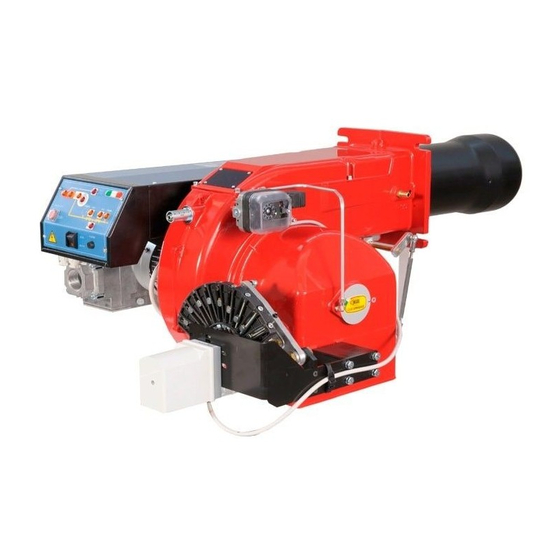
Burner data plate Type Gas - Light oil burners For the following information, please refer to Model Year European Directives the data plate: S.Number -Regulation 2016/426/UE (appliances burning gaseous fuels) burner type and burner model: must be Output Oil Flow -2014/35/UE (Low Tension Directive) reported in any communication with the Fuel... - Page 5 PART I: SPECIFICATIONS PART I: SPECIFICATIONS BURNERS FEATURES Fig. 1 Note: the figure is indicative only. Control panel with startup switch Gas valves group Electrical panel Air tank Blast tube + Combustion head Flange Adjusting cam (progressive/fully modulating burners only) Air pressure switch Gas operation: the gas coming from the supply line, passes through the valves group provided with filter and stabiliser.
-
Page 6: Gas Connection
Burners are identified by burner type and model. Burner model identification is described as follows. Type Model MD. S. 1 BURNER TYPE P61 - P65 - P71 2 FUEL M - Natural gas L - LPG B - Biogas C - Town gas... -
Page 7: Technical Specifications
PART I: SPECIFICATIONS Technical Specifications BURNER TYPE P61 M-.. P61 L-... 160 - 800 Output min. - max. kW Natural gas L.P.G. Fuel Category see next paragraph 3B/P 17 - 85 6 - 30 Gas flow rate min.-max. Stm (see Note 2) Gas pressure min.-max. - Page 8 PART I: SPECIFICATIONS BURNER TYPE M-...0.xx L-...0.xx 300 - 1.200 Output min. - max. kW Natural gas L.P.G. Fuel Category see next paragraph 3B/P 11 - 45 32 - 127 Gas flow rate min.-max. Stm (see Note 2) Gas pressure min.-max.
- Page 9 Overall dimensions (mm) Burner: P61 Boiler recommended drilling template and burner flange B*: SPECIAL blast tube lengths must be agreed with Cib Unigas A(S*) A(L*) AA B(S*) B(L*) BB P61 PR - 0.32 1079 1169 736 298 812 184 204 P61 MD - 0.32...
- Page 10 Burners: P65 - P71 O min. O max. Boiler recommended drilling template and burner flange B*: SPECIAL blast tube lengths must be agreed with Cib Unigas A(S*) A(L*) B(S*) B(L*) Omin Omax 32 1129 1219 130 326 416 373 803 316 900...
- Page 11 A(S*) A(L*) AA B(S*) B(L*) BB Omin Omax Y(*S) Y(*L) 1188 1298 130 385 495 373 803 316 332 234 264 208 300 376 M10 330 233 457 130 327 519 531 198 212 155 P71 PR - 0.40 1188 1298 130 385 495 373 803 316 1026 332 234 264 208 300 376 M10 330 233 457 130 327 519 531 198 212 155...
- Page 12 PART I: SPECIFICATIONS How to read the burner “Performance curve” To check if the burner is suitable for the boiler to which it must be instal- Campo di lavoro bruciatori lled, the following parameters are needed: Tipo P60 Mod. M-xx.x.IT.A.0.50 - M-.xx.x.IT.A.0.65 furnace input, in kW or kcal/h (kW = kcal/h/860);...
-
Page 13: Performance Curves
PART I: SPECIFICATIONS Performance Curves P71 ..0.xx P71 ..1.xx To get the input in kcal/h, multiply value in kW by 860. Data are referred to standard conditions: atmospheric pressure at 1013mbar, ambient temperature at 15° C NOTE: The performance curve is a diagram that represents the burner performance in the type approval phase or in the laboratory tests, but does not represent the regulation range of the machine. - Page 14 PART I: SPECIFICATIONS Pressure in the Network / gas flow rate curves Natural Gas burners P61 M-.. Gas rate Stm P65 M-... Gas rate Stm P71 M-...0.xx P71 M-...1.xx Gas rate Stm Gas rate Stm ATTENTION: the gas rate value is quoted on the x-axis, the related network pressure is quoted on the y-axis (pressure value in the combustion chamber is not included).
- Page 15 PART I: SPECIFICATIONS Pressure in the Network / gas flow rate curves L.P.G. Burners P61 L-.. P65 L-.. Rp 1"¼ (32) Rp 1"¼ (32) Rp 1"½ (40) Rp 1"½ (40) Rp 2" (50) Rp 2" (50) DN65 DN65 4 6 8 10 12 14 16 18 20 22 24 26 28 30 32 34 36...
- Page 16 PART I: SPECIFICATIONS Combustion head gas pressure curves Combustion head gas pressure depends on gas flow and combustion chamber backpressure. When backpressure is subtracted, i depends only on gas flow, provided combustion is properly adjusted, flue gases residual O2 percentage complies with “Recommended combustion values”...
- Page 17 PART I: SPECIFICATIONS Pressure - rate in combustion head curves (natural gas) Curves are referred to pressure = 0 mbar in the combustion chamber! Natural Gas burners P61 M- Gas rate Stm P65 M- Gas rate Stm P71 M-...0.xx P71 M-...1.xx...
- Page 18 (LPG) Pressure - rate in combustion head curves Curves are referred to pressure = 0mbar in the combustion chamber! P61 L-.. P65 L-.. 8 10 12 14 16 18 20 22 24 26 28 30 32 8 10 12 14 16 18 20 22 24 26 28 30 32 34 36 38 40...
- Page 19 Packing The burners are despatched in wooden crates whose dimensions are: P61: 1200mm x 670mm x 540mm (L x P x H). P65 - P71 - : 1280mm x 850mm x 760mm (L x P x H).
- Page 20 PART II: INSTALLATION Keys 1 Burner 2 Fixing nut 3 Washer 4 Ceramic fibre plait 5 Stud bolt 7 Blast tube The burner is designed to work positioned according to the picture below. For different installations, please contact the Technical Department.
-
Page 21: Gas Inlet
PART II: INSTALLATION Gas train with valves group MB-DLE (2 valves + gas filter + pressure governor) + VPS504 gas proving system BY OTHERS BY BURNER CONSTRUCTOR GAS INLET Filter Butterfly valve Pressure switch - PGMIN Main burner Safety valve with built in gas governor Bellows unit(*optional) Proving system (*optional) Manual valve(*optional) - Page 22 PART II: INSTALLATION GAS TRAIN CONNECTIONS The diagrams show the components of the gas trai included in the delivery and which must be fit- ted by the installer.The diagrams are in compliance with the current laws. Procedure to install the double gas valve unit: - two (2) gas flanges are required;...
-
Page 23: Assembling The Gas Train
PART II: INSTALLATION MultiBloc MB-DLE - Assembling the gas train F”direction” arrows for gas supply network installation Keys 1 Gasket 2 Gas filter 3 Gas valves group 4 Bellows unit 41Manual valve MULTIBLOC DUNGS MB-DLE 405..412 Mounting 1. Mount flange onto tube lines: use appropriate sealing agent (see Fig. 4); 2. - Page 24 PART II: INSTALLATION MultiBloc MBE ALLA V. FARFALLA Example of gas train MBE 501939 GAS BRUCIATORE ø185 VD-R VD-V VD-R VD-V Gas filter PGMAX PGMAX PGMI PGMIN PS pressure sensor PGCP PGCP ATTENTION: once the gas train is mounted according, the gas proving test mus be performed, according to the procedure set by the laws in force.
- Page 25 PART II: INSTALLATION Mounting VD-R & PS-... ActuatorVD-R ActuatorVD-V The actuator VD-V does not need any adjustment (funzione M12 x 5 Pin ON-OFF) The actuator VD-R It must be combined with the PS sensor (include regolatore di pressione) The PS sensor chosen based on the necessary pressure ...
-
Page 26: Electrical Connections
PART II: INSTALLATION ELECTRICAL CONNECTIONS WARNING! Respect the basic safety rules. make sure of the connection to the earthing system. do not reverse the phase and neutral connections. fit a differential thermal magnet switch adequate for connection to the mains. WARNING! before executing the electrical connections, pay attention to turn the plant’s switch to OFF and be sure that the burner’s main switch is in 0 position (OFF) too. - Page 27 PART III: OPERATION PART III: OPERATION DANGER! Incorrect motor rotation can seriously damage property and injure people.WARNING: before starting the burner up, be sure that the manual cutoff valves are open and check that the pressure upstream the gas train complies the value quoted on paragraph “Technical specifications”.
-
Page 28: Gas Operation
PART III: OPERATION Fig. 10 - Burner front panel Keys A1 Burner Modulator (only on fully modulating burners) B1 Lock-out LED B2 Hi-flame operation LED B3 Lo-flame operation LED B4 “Ignition transformer operation” LED B5 “Fan motor overload tripped” LED G1 “EV2 opening”... -
Page 29: Adjusting Procedure
PART III: OPERATION ADJUSTING AIR AND GAS FLOW RATES WARNING! During commissioning operations, do not let the burner operate with insufficient air flow (danger of formation of carbon monoxide); if this should happen, make the fuel decrease slowly until the normal combustion values are achieved. - Page 30 PART III: OPERATION Siemens VGD.. Dungs Multibloc Pressure governor is factory-set. The setting values must be locally adapted to machine conditions. Important! Follow the instruc- tions carefully! .To adjust the air flow rate in the high flame stage, loose the RA nut and screw VRA as to get the desired air flow rate: moving the rod T towards the air damper shaft, the air damper opens and consequently the air flow rate increases, moving it far from the shaft the air damper closes and the air flow rate decreases.
- Page 31 PART III: OPERATION If it is necessary to change the burner output in the low flame stage, move the low flame cam: the low flame position matches the ignition position. As far as burners fitted with Dungs MBC gas valves, the low flame cam does not match the ignition cam position, that is why it must be set at about 30°...
- Page 32 PART III: OPERATION Progressive burners Once the procedure till step 8 described is accomplished, go on as follows: set the low flame cam matching the high flame cam; 10 set the TAB thermostat to the minimum in order that the actuator moves progressively towards the low flame position; The manual air damper control is not provided on these actuators.
- Page 33 PART III: OPERATION Fully modulating burners To adjust the fully-modulating burners, use the S3 switch on the burner control panel (see next picture), instead of the TAB thermostat as described on the previous paragraphs about the progressive burners. Go on adjusting the burner as described before, paying attention to use the CMF switch intead of TAB.
- Page 34 PART III: OPERATION MultiBloc MBE Pressure taps 1, 2, 3, 5 Sealing plug For system accessories Fig. 14 Adjusting the gas valves group Multibloc MB-DLE VS T(VR) The multibloc unit is a compact unit consisting of two valves, gas pressure switch, pres- sure stabilizer and gas filter.
- Page 35 PART III: OPERATION Output flange 1 Electrical connection for valves 10 Test point connection M4 downstream of valve 2 2 Operation display (optional) 11 Gas flow direction 3 Pressure governor closing tap 12 Test connection G 1/8 downstream of valve 1, on both sides 4 Start setting cap 13 Vent nozzle pressure regulator 5 Hydraulic brake and rate regulator...
- Page 36 The adjusting plate correct position must be regulated in the plant during the commissioning. As far as the plate adjustments, insert a 1,5mm (P61, P65), 1.4mm (P71), 1.7mm (P73A) sized rod iron and close as shown on the next pictures.
- Page 37 PART III: OPERATION Calibration air and gas pressure switches The air pressure switch locks the control box if the air pressure is not the one requested. If it happens, unlock the burner by means of the control box unlock pushbutton, placed on the bur- ner control panel.
-
Page 38: Routine Maintenance
PART IV: MAINTENANCE PART IV: MAINTENANCE At least once a year carry out the maintenance operations listed below. In the case of seasonal servicing, it is recommended to carry out the maintenance at the end of each heating season; in the case of continuous operation the maintenance is carried out every 6 months. - Page 39 PART IV: MAINTENANCE MultiBloc MBE MultiBloc VD Mounting to push position 1. Position VD on VB, fig. 2+3. 2. Slide VD forward up to the stop, fig. 4. 3. Screw VD on with 2 M5 screws for each, max. 5 Nm/44 in.-lb., fig. 5/6. 4.
- Page 40 PART IV: MAINTENANCE Removing the combustion head Type P61 Remove cover C. Unscrew the two screws S holding in position the washer and then unscrew VRT to free the threaded rod AR. Unscrew the screws V holding in position the ...
-
Page 41: Replacing The Electrodes
PART IV: MAINTENANCE Replacing the electrodes ATTENTION: avoid the ignition and detection electrodes to contact metallic parts (blast tube, head, etc.), otherwise the boiler’s operation would be com- promised. Check the electrodes position after any intervention on the com- bustion head. To replace the electrodes: Remove the cover ... -
Page 42: Wiring Diagrams
PART IV: MAINTENANCE Checking the detection current with photocell (LME) (L.P.G.) (QRA - only for P71 GPL) 3 x 1,5 mm QRA5... AGM19 Schermatura Max. 60 m Legenda A Amperometro RAR9… Rivelatore con fotocellula al silicio ION Sonda di ionizzazione Burner service term - In optimal operating conditions, and with preventive maintenance, the burner can last up to 20 years. - Page 43 PART IV: MAINTENANCE TROUBLESHOOTNG GUIDE Gas operation * No electric power supply * Restore power supply * Main switch open * Close switch * Thermostats open * Check set points and thermostat connections * Bad thermostat set point or broken thermostat * Reset or replace the thermostat * No gas pressure * Restore gas pressure...
- Page 44 BURNER EXPLODED VIEW P61 - P65 - P71 Pos. Description Pos. Description 11.2.4 TRANSMISSION AIR ADJUSTING CAM MOTOR 11.2.5 CONNECTING ROD VALVE GROUP 11.2.6 THREADED PIPE 11.2.7 JOINT ELBOW 11.2.8 ROD JOINT M/F REDUCTION 11.3 INDEX PLATE VALVE GROUP FLANGE 11.4...
-
Page 51: Start-Up Program
APPENDIX SIEMENS LME11/21/22 CONTROL BOX tion of «t11») with the LME22..., fan motor «M» will be started. Waiting time Preconditions for burner startup During the waiting time, air pressure monitor «LP» and flame relay «FR» Burner control must be reset are tested for correct contact positions. - Page 52 LME11 control sequence LME21 control sequence B´ B´ SB / R SB / R W / GP W / GP (LR) BV2 7101d05/0206 Control sequence Waiting time LME22 control sequence Purge time B´ TSA Ignition safety time SB / R Preignition time W / GP Postignition time...
- Page 53 LME11 connection diagram Connection diagram Error message (alarm) Fuel valve PC control EK2 Remote lockout reset button RESET Flame signal Gas pressure switch Air pressure switch Load controller K2/1 K2/2 Fan motor Control thermostat/pressurestat Safety limit thermostat R / W Limit thermostat /pressure switch Ignition transformer 7101 24 /0606...
- Page 54 CONTROL PROGRAM IN THE EVENT OF FAULT CONTROL BOX LOCKED If a fault occurs, all outputs will immediately be deactivated (in less In the event of lockout, the LME.. remains locked and the red signal lamp than 1s). (LED) will light up.The burner control can immediately be reset. This state After an interruption of power, a restart will be made with the full pro- is also mantained in the case fo mains failure.
- Page 56 C.I.B. UNIGAS S.p.A. Via L.Galvani, 9 - 35011 Campodarsego (PD) - ITALY Tel. +39 049 9200944 - Fax +39 049 9200945/9201269 web site: www.cibunigas.it - e-mail: cibunigas@cibunigas.it Note: specifications and data subject to change. Errors and omissions excepted.
Need help?
Do you have a question about the P61 and is the answer not in the manual?
Questions and answers