Table of Contents
Advertisement
Quick Links
PBY90 - PBY91
PBY92 - PBY93
PBY510 - PBY515
PBY520 - PBY525
Progressive, Fully-modulating
with pneumatic atomization
(LMV2x/3x micro-processor control)
MANUAL OF INSTALLATION - USE - MAINTENANCE
BURNERS - BRUCIATORI - BRULERS - BRENNER - QUEMADORES - ГОРЕЛКИ
Heavy oil Burners
Rel. 1.0
M039397CA
04/2020
Advertisement
Table of Contents

Subscribe to Our Youtube Channel
Related Manuals for Unigas PBY93


Summary of Contents for Unigas PBY93
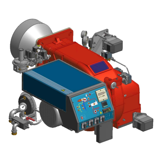
- Page 1 PBY90 - PBY91 PBY92 - PBY93 PBY510 - PBY515 PBY520 - PBY525 Progressive, Fully-modulating Heavy oil Burners with pneumatic atomization (LMV2x/3x micro-processor control) MANUAL OF INSTALLATION - USE - MAINTENANCE BURNERS - BRUCIATORI - BRULERS - BRENNER - QUEMADORES - ГОРЕЛКИ...
-
Page 2: General Introduction
DANGERS, WARNINGS AND NOTES OF CAUTION THIS MANUAL IS SUPPLIED AS AN INTEGRAL AND ESSENTIAL PART OF THE PRODUCT AND MUST BE DELIVERED TO THE USER. INFORMATION INCLUDED IN THIS SECTION ARE DEDICATED BOTH TO THE USER AND TO PERSONNEL FOLLOWING PRODUCT INSTALLATION AND MAINTENANCE. -
Page 3: Directives And Standards
bare feet; DIRECTIVES AND STANDARDS do not pull electric cables; Gas burners European directives do not leave the equipment exposed to weather (rain, sun, etc.) -2009/142/EC (Gas Directive) unless expressly required to do so; -2014/35/UE (Low Tension Directive) do not allow children or inexperienced persons to use equipment; -2014/30/UE (Electromagnetic compatibility Directive) The unit input cable shall not be replaced by the user. -
Page 4: Symbols Used
-EN 60204-1:2006 (Safety of machinery – Electrical equipment of machi- nes.) Failure to observe the warning may -CEI EN 60335-1 (Specification for safety of household and similar electri- result in serious injuries or death. DANGER! cal appliances); -CEI EN 60335-2-102 (Household and similar electrical appliances. Safety. -
Page 5: General Features
PART I: SPECIFICATIONS PART I: INSTALLATION GENERAL FEATURES This particular burner series has been studied to use compressed air or alternatively steam, to atomize heavy oil. In this way we have achieved higher efficiency compared to mechanical atomization. These burners are equipped with a low pressure nozzle which permits to save fuel and, above all, to preserve the whole system. -
Page 6: Burner Model Identification
Burners are identified by burner type and model. Burner model identification is described as follows. Type Model PBY90 PR. S. (1) BURNER TYPE PBY90, PBY91, PBY92, PBY93, PBY510, PBY515, PBY520, PBY525 (2) FUEL H - heavy oil, max viscosity 4000cSt (530°E) @ 50°C (3) OPERATION (Available versions) PR - Progressive MD - Fully modulating... - Page 7 BURNER PBY510 PBY515 PBY520 PBY525 1100 - 5000 1200 - 6000 1200 - 6500 1800 - 7300 Output min ÷ max kW Heavy oil Fuel See “Burner model identification” table Oil viscosity min. ÷ max. kg/h 98 - 446 107 - 535 107 - 579 160 - 651 Heavy oil rate...
- Page 8 Overall dimensions (mm) 45° Reccomended counterflange Burner flange boiler recommended drilling template PBY90, PBY91, PBY92, PBY93: A COUNTERFLANGE IS MANDATORY:a gasket must be placed between the generator and the counterflange PBY90 1282 237 525 1158 647 468 M12 280 228 185...
- Page 9 PBY510 374 * 1326 1249 boiler recommended drilling template Burner flange...
- Page 10 PBY515, PBY520, PBY525 Burner flange boiler recommended drilling template Reccomended counterflange A COUNTERFLANGE IS MANDATORY:a gasket must be placed between the generator and the counterflange A (AS) A (AL) AB AD AE B (BS) B (BL) RR SS T 1331 1511 35 584 265 454 466 570 1249 605 644 474 540 492 M16 390 114 93 43 535 329 761 270...
- Page 11 Fig. 2 - (3I2D-03 v4) Hydraulic diagram compressed air oil inlet to the tank combustion air natural gas / LPG SUPPLIED LOOSE ITEMS ON BOARD ITEMS BY OTHERS BY BURNER CONSTRUCTOR LPG gas - out of Cib Unigas scope of supply...
- Page 12 COMPRESSED AIR TRAIN (ATOMIZATION) Pressure governor with filter Pressure gauge Solenoid valve Pressure switch One-way valve Metering valve Manual valve Pressure gauge Flexible hose The following items are out of CIB UNIGAS scope of supply NOTE 77 - 78 - 79...
-
Page 13: Performance Curves
How to read the burner “Performance curve” To check if the burner is suitable for the boiler to which it must be instal- Campo di lavoro bruciatori lled, the following parameters are needed: Tipo P60 Mod. M-xx.x.IT.A.0.50 - M-.xx.x.IT.A.0.65 furnace input, in kW or kcal/h (kW = kcal/h / 860); backpressure (data are available on the boiler ID plate or in the user’s manual). - Page 14 PBY510 PBY515 1000 1500 2000 2500 3000 3500 4000 4500 5000 5500 1 000 1 500 2000 2500 3000 3500 4000 4500 5000 5500 6000 6500 PBY520 PBY525 1 000 1 500 2000 2500 3000 3500 4000 4500 5000 5500 6000 6500 1 000 1 500 2000 2500 3000 3500 4000 4500 5000 5500 6000 6500 7000 7500 To get the input in kcal/h, multiply value in kW by 860.
- Page 15 PART II: INSTALLATION MOUNTING AND CONNECTING THE BURNER Packing Burners are despatched in wooden crates whose dimensions are: PBY90-91-92-93: 1730 mm x 1280 mm x 1020 mm(L x P x H) PBY510-515-520-525: 1730 mm x 1430 mm x 1130 mm(L x P x H) Packing cases of this kind are affected by humidity and are not suitable for stacking.
- Page 16 Fitting the burner to the boiler To install the burner into the boiler, proceed as follows: make a hole on the closing door of the combustion chamber as described on paragraph “Overall dimensions”) place the burner to the boiler: lift it up and handle it according to the procedure described on paragraph “Handling the burner”; place the 4 stud bolts (5) on boiler’s door, according to the burner drilling template described on paragraph “Overall dimensions”;...
- Page 17 spacer to move the burner backwards or to design a blast tube tha suites the utilisation (please, contact the manifacturer). a) Heat output in kW b) Lenght of the flame tube in meters c) Flame tube firing intensity in MW/m d) Combustion chamber diameter (m) Fig.
-
Page 18: Connecting The Pump
OIL TRAIN CONNECTIONS About the use of fuel pumps Do not use fuel with additives to avoid the possible formation over time of compounds which may deposit between the gear teeth, thus obstructing them. After filling the tank, wait before starting the burner. This will give any suspended impurities time to deposit on the bottom of the tank, thus avoiding the possibility that they might be sucked into the pump. - Page 19 Heavy oil pumps The pump provided with the burner must be installed according to the hydraulic diagram. capacity power speed max outlet pressure max inlet pressure Pumps connection [l/h] [kW] [rpm] [bar] (bar) Kral KF 10 BCB 0,37 1500 DN25 Kral KF 15 BCB 0,55 1500...
- Page 20 Connecting the compressed air hoses To connect the compressed air supply, refer to the following pictures Flow governor with filter...
- Page 21 Pilot gas train The connection to the pilot gas train must be done according to the following scheme, valid for LPG. In case of natural gas, connect the pressure goveror (pos. 3) to the natural gas line (maximum input pressure = 1 bar). MANUFACTURER INSTALLER (1) Gas valves...
-
Page 22: Electrical Connections
ELECTRICAL CONNECTIONS Respect the basic safety rules. make sure of the connection to the earthing system. do not reverse the phase and neutral connections. fit a differential thermal magnet switch adequate for connection to the mains. ATTENTION: before executing the electrical connections, pay attention to turn the plant’s switch to OFF and be sure that the burner’s main switch is in 0 position (OFF) too. - Page 23 Rotation of electric motor Once the electrical connection of the burner is executed, remember to check the rotation of the electric motor. The motor should rotate according to the “arrow” symbol on the body. In the event of wrong rotation, reverse the three-phase supply and check again the rota- tion of the motor.
- Page 24 Recommendations to design heavy oil feeding plants This paragraph is intended to give some suggestions to make feeding plants for heavy oil burners. To get a regular burner operation, it is very important to design the supplying system properly. Here some suggestions will be mentioned to give a brief description. The term “heavy oil”...
- Page 25 Viscosity units conversion table Saybolt Cinematics Saybolt Redwood Engler Degrees Seconds Redwood Seconds viscosity Seconds Seconds no.1 (°E) Universal no..2 (Admiralty) Centistokes (cSt) Furol (SSF) (Standard) (SSU) 2.56 1.16 32.1 1.31 36.2 1.58 44.3 5.83 10.3 1.88 52.3 6.77 13.1 2.17 12.95 60.9...
- Page 26 VISCOSITY vs TEMPERATURE DIAGRAM FOR COMBUSTIBLE OILS 1000 PUMPING LIMIT TEMPERATURE (°C) LIGHT OIL 1,3°E AT 20°C HEAVY OIL 2,4°E AT 50°C HEAVY OIL 4°E AT 50°C HEAVY OIL 7,5°E AT 50°C HEAVY OIL 10°E AT 50°C HEAVY OIL 13°E AT 50°C HEAVY OIL 22°E AT 50°C HEAVY OIL 50°C HEAVY OIL 47°E AT 50°C...
- Page 27 Indicative diagram showing the oil temperature at burner pump inlet vs. oil viscosity Example: if the oil has a 50°E @ 50°C viscosity, the oil temperature at the pump inlet should be 80°C (see diagram). OIL TEMPERATURE FOR PUMP FEEDING TEMPERATURE (°C) Fig.
- Page 29 PART III: OPERATION LIMITATIONS OF USE THE BURNER IS AN APPLIANCE DESIGNED AND CONSTRUCTED TO OPERATE ONLY AFTER BEING CORRECTLY CONNEC- TED TO A HEAT GENERATOR (E.G. BOILER, HOT AIR GENERATOR, FURNACE, ETC.), ANY OTHER USE IS TO BE CONSIDE- RED IMPROPER AND THEREFORE DANGEROUS.
-
Page 30: Control Panel
Control panel High flame lamp Low flame lamp Ignition transformer lamp Fan motor thermal cutout lamp Burner lockout lamp Burner stand-by lamp Solenoid valve lamp Compressed air pressure switch lamp Compressed air solenoid valve lamp Heating resistors safety thermostat lamp Plant enabling thermostat lamp Siemens output controller Oil pump in operation... -
Page 31: Air Vent
ADJUSTMENT FOR OIL OPERATIONS Before starting up the burner, make sure that the return pipe to the tank is not obstructed. Any obstruction would cause the pump seal to break. ATTENTION: before starting the burner up, be sure that the manual cutoff valves are open. Be sure that the mains switch is closed. - Page 32 Compressed air adjustment ATTENTION: set the pressure value about 1 bar, at the pressure gauge 47 (see Fig. 17). check it before open valve 16! To start the burner set the oil and atomisation medium pressure at about 1 bar, as first trial. then, regulate the burner checking the com- bustion values at the chimney, according to the paragraph "operation", and adjust the starting point according to the regulation.
- Page 33 Oil Flow Rate Settings actuator Turn the burner on by means of the main switch on the burner control panel (see chapter “Operation”); with the electrical panel open, prime the oil pump acting directly on the related contactor CP (see next picture): check the pump motor rotation and keep pressing for some seconds until the oil circuit is charged;...
- Page 34 If necessary, change the combustion head position: to let the burner operate at a lower output, move progressively back the com- bustion head towards the MIN position, by turning clockwise the VRT ring nut. The graduated index ID shows the combustion head shifting (each mark refers to 5mm).
- Page 35 Fully-modulating burners To adjust the fully-modulating burners, use the CMF switch on the burner control panel (see next picture), instead of the TAB thermo- stat as described on the previous paragraphs about the progressive burners. Go on adjusting the burner as described before, paying attention to use the CMF switch intead of TAB.
- Page 36 Oil viscosity at 50 °C according to the letter shown in the burner model Menu path 89 cSt < 50 cSt > 50 cSt > 110 cSt > 400 cSt < 110 cSt < 400 cSt < 4000 cSt 12 °E <...
-
Page 37: User Interface
ADJUSTING AIR AND FUEL RATE Adjustments - brief description The air and fuel rates adjustments must be performed at the maximum ouptput first (“high flame”): see the LMV related manual. Check that the combustion parameters are in the suggested limits. Check the flow rate measuring it on the counter or, if it was not possible, verifying the combustion head pressure by means of a dif- ferential pressure gauge, as described on par. -
Page 38: Setting Menu
Info and Enter keys Used for Info and Service menues Used as Enter key in the setting modes Used as Reset key in the burner operation mode Used to enter a lower level menu -Key - Used to decrease a a value Used to enter Info and Serivce during the curve adjustments +Key + Used to increase a a value... - Page 39 During operation, the following program phases are shown. The meaning for each phase is quoted in the table below Fase /Phase Funzione Function Ph00 Fase blocco Lockout phase Ph01 Fase di sicurezza Safety phase Ph10 t10 = tempo raggiungimento posizione riposo t10 = home run Ph12 Pausa...
-
Page 40: Info Level
The burner and consequently the LMV2x.. are factory set; the air and fuel curves as set as well. Info level To enter the Info level, proceed as follows: in any menu position, press keys + and - at the same time, then the program will start again: the display will show OFF. until the display will show InFo, Press the enter (InFo) key then il will show the first code (167) flashing, on the right side it will show the data entered. - Page 41 The Info level shows some basic parameters as: Parameter Description Cubic meters of fule (resettable) Operating hours (resettable) Device operating hours Burners start-ups (resettable) Total number of start-ups Burner number (i.e. serial number) Software version Software date Device serial number Customer code Version Free...
-
Page 42: Service Level
If a message like the one below is shown during operation, it means that the burner is locked out and the Errore code is shown (in the example “error code:4”); this message is alternating with another message Diagnostic code (in the example “diagnostic code:3”). Record the codes and find out the fault in the Error table. To perform the reset, press InFo for one second: The unit displays an event which does not lead to shutdown. - Page 43 Parameter Description Flame intensity % output, if set = automatic operation Actuators position, 00=combustibile; 01= aria Lock-outs number 701..725 Lock-outs History (see chapter 23 in the LMV2x manual) the first parameter will be “954”: the percentage of flame is shown on the right. By pressinf + or - it is possible to scroll up/down the parameter list.
-
Page 44: Routine Maintenance
PART IV: MAINTENANCE At least once a year carry out the maintenance operations listed below. In the case of seasonal servicing, it is recommended to carry out the maintenance at the end of each heating season; in the case of continuous operation the maintenance is carried out every 6 months. - Page 45 filter slots Fig. 22 - threaded body Fig. 23 - threaded body without bottom cover Removing the combustion head Remove the cover H. Slide the photoresistor out of its housing. Unscrew the flexible hoses from the gun (burner side) and remove the whole assembly as shown on Fig. 24. Fig.
- Page 46 Fig. 25 To change the nozzle position, please contact the Technical Dpt. xBY5xx PBY9x...
-
Page 47: Seasonal Stop
Checking the detection current .To check the detection signal follow the scheme in the picture below. If the signal is less than the value indicated, check the position of the detection electrode or detector, the electrical contacts and, if necessary, replace the electrode or the detector. Device Minimum detection signal Flame detector... -
Page 48: Wiring Diagrams
WIRING DIAGRAMS Refer to the attached wiring diagrams. WARNING 1 - Electrical supply 230V 50Hz 1 a.c./400V 50Hz 3N a.c. 2 - Do not reverse phase with neutral 3 - Ensure burner is properly earthed... -
Page 51: Troubleshooting
TROUBLESHOOTING Heavy oil operation MAIN SWITCH OPEN LINE FUSE INTERVENTION MAX. PRESSURE SWITCH FAULT FAN THERMAL CUTOUT INTERVENTION AUXILIARY RELAIS FUSES INTERVENTION CONTROL BOX FAULT SERVOCONTROL FAULT SMOKEY FLAME IGNITION TRANSFORMER FAULT IGNITION ELECTRODE DIRTY OR WRONG POSI- TIONED DIRTY NOZZLE FUEL SOLENOID VALVE DEFECTIVE PHOTORESISTOR DIRTY OR DEFECTIVE HI-LO FLAME THERMOSTAT DEFECTIVE... - Page 52 C.I.B. UNIGAS S.p.A. Via L.Galvani, 9 - 35011 Campodarsego (PD) - ITALY Tel. +39 049 9200944 - Fax +39 049 9200945/9201269 web site: www.cibunigas.it - e-mail: cibunigas@cibunigas.it Note: specifications and data subject to change. Errors and omissions exceptd.
- Page 53 AZL2x - LMV2x/3x Burner Management System Service manual 03/2023 M12916CD Rev. 3.4...
- Page 54 INDEX MICROPROCESSOR CONTROLLED SYSTEM..........................6 User interface....................................6 Parameters level (heating engineer)............................... 8 Setting menu....................................9 Block 000: Internal Parameter ..............................10 Block 100: General information..............................10 Block 200: Burner control................................13 Block 400: Setting air/fuel ratio curves............................25 Block 500: Air/fuel ratio control ..............................26 Block 600: Actuators ..................................
- Page 55 DANGERS, WARNINGS AND NOTES OF CAUTION THIS MANUAL IS SUPPLIED AS AN INTEGRAL AND ESSENTIAL PART OF THE PRODUCT AND MUST BE DELIVERED TO THE USER. INFORMATION INCLUDED IN THIS SECTION ARE DEDICATED BOTH TO THE USER AND TO PERSONNEL FOLLOWING PRO- DUCT INSTALLATION AND MAINTENANCE.
- Page 56 DIRECTIVES AND STANDARDS do not leave the equipment exposed to weather (rain, sun, etc.) unless expressly required to do so; Gas burners European directives: do not allow children or inexperienced persons to use equipment; - Directive 2009/142/EC - Gas Appliances; The unit input cable shall not be replaced by the user.
- Page 57 -EN 55014-1Electromagnetic compatibility - Requirements for household appliances, electric tools and similar apparatus. -UNI EN 676 (Gas Burners; -CEI EN 60335-1(Household and similar electrical appliances - Safety. Part 1: General requirements; - EN 50165 Electrical equipment of non-electric appliances for household and similar purposes.
- Page 58 MICROPROCESSOR CONTROLLED SYSTEM The control system is made of the Siemens LMV central unit that performs all the burner control functions and of the Siemens AZL local programming unit that interfaces the system with the user. Keys Burner AZL2.. Air actuator Fuel actuator LMV2..
- Page 59 The keys functions are the following: Key F Used to adjust the “fuel” actuator position (Fuel): : While pressing the F key, the “fuel” actuator position can be changed by means of the + and - keys. Key A Used to adjust the “air” actuator position (Air): While pressing the A key, the “air”...
- Page 60 Parameters level (heating engineer)
- Page 61 Setting menu The seeting menu is divided into different blocks: Bloc. Descrizione Description Password Internal parameters OEM / Service Informazioni generali General OEM / Service / Info Controllo bruciatore Burner control OEM / Service Controllo bruciatore (solo LMV26) Burner control (LMV26 only) OEM / Service Curve rapporto Ratio curves...
- Page 62 Block 000: Internal Parameter Param. Descrizione Description Password Password livello assistenza (ingegnere del Password heating engineer (4 characters) calore) Password livello OEM (costruttore del brucia- Password OEM (5 characters) tore) Start backup / restore via AZL2.../ PC sof- tware (set parameter to 1) Index 0: Create backup Index 1: Execute restore Error dia- Start backup/restore via AZL2x/PC gnostics via negative values...
- Page 63 Frequenza di rete Mains frequency 0 = 50 Hz 0 = 50 Hz Service / Info 1 = 60 Hz 1 = 60 Hz Luminosità display Display brightness Service / Info Tempo dopo il quale, se non viene premuto nessun tast il software esce dalla modalita Timeout for menu operation (default value = programmazione (valore fabbrica = 60min - 60min - range: 10 - 120 min)
- Page 64 Numero totale di partenze (non azzerabile) Total number of startups Service / Info Volume combustibile (azzerabile da OEM) Fuel volume (resettable by OEM) Service / Info Fuel 1(secondo combustibile)Ore di eserci- Fuel 1: Operation hours resettable Service / Info zio (azzerabile da Service) Fuel 1 (secondo combustibile) Numero di Fuel 1: Number of startups resettable Service / Info...
- Page 65 Block 200: Burner control Param. Descrizione Description Password Modalità funzionamento bruciatore ( rampa Burner operating mode (fuel train, modula- combustibile, modulante / multistadio, servo- ting / multistage, actuators, etc..) comandi, ecc.) __= non definito (cancellazione curve) __= undefined (delete curves) 1 = accensione diretta a gas (G mod) 1 = gas direct ignition (G mod) 2 = accensione tramite pilota gas con attacco...
- Page 66 15 = gas rampa Gp1 modulante pneumatico 15 = Gp1 mod pneu without actuator senza servomotori (Gp1 mod pneu) 16 = Gp2 mod pneu without actuator 16 = gas rampa Gp2 modulante pneumatico 17 = Lo 2-stage without actuator senza servomotori (Gp2 mod pneu) 18 = Lo 3-stage without actuator 17 = olio LO 2 stadi senza servomotori 19 = G mod gas actuator only...
- Page 67 Gas: sonda rilevazione fiamma attivo (valore Gas: active detector flame evaluation (default fabbrica = 1) value = 1) OEM / Service 0 = QRB../QRC.. 1 = ION / QRA.. Gas: Preventilazione (valore fabbrica = 1) Gas: Pre-purging (default value = 1) 1 = attivo 1 = active 0 = non attivo...
- Page 68 Gas: Pressostato gas di minima (default = 1) Gas: Pressure switch-min input 0 = inattivo 0 = inactive 1 = pressostato gas di minima (a monte val- 1 = pressure switch-min (upstream of fuel vola V1) valve 1 (V1)) 2 = controllo perditavalvole via pressostato 2 = valve proving via pressure switch-min OEM / Service (montato tra le valvole V1 e V2)
- Page 69 Gas: tempo pressione atmosferica controllo Gas: proving test time atmospheric pres- tenuta (valore fabbrica = 10s - range impo- sure (default value = 10s - range:0.2s - 60s) stazione:0.2s - 60s) Gas: tempo riempimento controllo tenuta Gas: proving test filling time (default value = (valore fabbrica = 3s - range imposta- 3s - range:0.2s - 10s) zione:0.2s - 10s)
- Page 70 Olio: Intervallo 1 (valore fabbrica = 2s - Oil: Interval 1 (default value = 2s - OEM / Service range impostazione:0.2s - 60min) range:0.2s - 60min) Olio: tempo di sicurezza 2 (TSA2) (valore Oil: safety time 2 (TSA2) (default value = 3s fabbrica = 3s - range impostazione:0.2 - 10s) - range:0.2 - 10s) Olio: Intervallo 2 (valore fabbrica = 2s -...
- Page 71 Block 300: Burner control (only with LMV26) Param. Descrizione Description Password Combustibile 1 : Modalità funzionamento bru- Fuel 1 : Burner operating mode (fuel train, ciatore ( rampa combustibile, modulante / modulating / multistage, actuators, etc..) multistadio, servocomandi, ecc.) __= non definito (cancellazione curve) __= undefined (delete curves) 1 = accensione diretta a gas (G mod) 1 = gas direct ignition (G mod)
- Page 72 11 = olio 2 stadi con accensione tramite pilota 11 = LoGp 2-stage (LOGp 2-stage) 12 = Lo mod 2 fuel valves 12 = olio modulante con 2 valvole combusti- 13 = LoGp mod 2 fuel valves bile (LOmod 2 valvole) 14 = G mod pneu without actuator 13 = olio modulante con 2 valvole combusti- 15 = Gp1 mod pneu without actuator...
- Page 73 Combustibile 1 - Gas: tempo di preaccen- Fuel 1 - Gas: Preignition time (default value = sione (valore fabbrica = 2s - range imposta- 2s - range: 0.2s - 60min) OEM / Service zione:0.2s - 60min) Combustibile 1 - Gas: tempo di sicurezza 1 Fuel 1 - Gas: Safety time 1 (TSA1) (default (TSA1) (valore fabbrica = 3s - range impo- value = 3s - range: 0.2 - 10s)
- Page 74 Limite ripetizioni perdita di fiamma (valore Repetition limit loss of flame (default value= 2 fabbrica = 2 - range impostazione:1 - 2) - range:1 - 2) Fuel 1 - Gas: execution proving test (default Combustibile 1 - Gas: esecuzione controllo value= 2) tenuta (valore fabbrica = 2) 0 = no controllo tenuta...
- Page 75 Fuel 1 - Oil: prepurging (default value = 1) Combustibile 1 - Olio: preventilazione (valore fabbrica = 1) 0 = deactivated 1 = attivo 1 = activated 0 = non attivo 0 = deactivated OEM / Service In ambito civile la norma EN267 rende obbli- WARNING: in the civil field, the prepurge is gatoria la preventilazione.
- Page 76 Limite ripetizioni perdita di fiamma (valore Repetition limit value loss of flame (default fabbrica = 2 - range impostazione:1 - 2) value = 2 - range:1 - 2) Fuel 1 - Oil: time oil ignition (default value = Combustibile 1 - Olio: tempo iniezione olio (valore fabbr.
- Page 77 Block 400: Setting air/fuel ratio curves Param. Descrizione Description Password Curve controllo servocomando combustibile Ratio control curve fuel actuator (F): it acces- (F): si accede alla lista dei punti da impostare ses to the parameter list of the points to be set OEM / Service (da P0 a P9) - consultare paragrafo “Imposta- (P0 to P9) - see paragrapf “Setting the curves”...
- Page 78 Block 500: Air/fuel ratio control Param. Descrizione Description Password No-flame position fuel actuator Posizione servocomando combustibile in assenza di fiamma (no-flame) Indice 0 = posizione di sosta = 0° Index 0 = no-load position = 0° OEM / Service Indice 1 = posizione preventilazione = 0° Index 1 = prepurge position = 0°...
- Page 79 Activation of VSD / PWM fan (PWM = Pulse- Width Modulation) Activation of VSD / PWM fan OEM / Service 0=deactived 1=actived (PWM = Pulse-Width Modulation) Parameter 544 Modulation Modulation Modulation Modulation Actuator Actuating speed param- Max. delta between the curve points eter 613 OEM / Service Actuator...
- Page 80 Block 600: Actuators Param. Descrizione Description Password Impostazione punto di riferimento Selection of reference point Indice 0 = combustibile Index 0 = fuel Indice 1 = aria Index 1 = air 0 = chiuso (<0°) 0 = closed (<0°) 1 = aperto (>90°) 1 = open (>90°) Direzione rotazione del servocomando Actuator’s direction of rotation...
- Page 81 Tipo di riferimento dei servocomandi index 0 = fuel (default = 0 (riferimento stan- dard) Type of referencing index 1 = air (default = 0 (riferimento stan- Index 0 = fuel dard) Index 1 = air 0 = standard 0 = standard 1 = fermo entro il raggio utile 1 = stop within usable range 2 = fermi interni (SQN1...)
- Page 82 Configurazione uscita analogica % di carico Configuration of analog output (default value (valore fabbrica = 0) = 0) 0 = DC 0..10 V 0 = DC 0..10 V OEM / Service 1 = DC 2..10 V 1 = DC 2..10 V 2 = DC 0/2..10 V 2 = DC 0/2..10 V ATTENTION: as for SQM3x actuators, set the direction according to the acutator function.
- Page 83 Block 700: Error history Param. Descrizione Description Password Storico errori: 701 - 725.01.codice Error history: 701 - 725.01.code Service / Info Storico errori: 701 - 725.02.codice diagnostico Error history: 701 - 725.02.diagnostic code ° Service / Info Storico errori: 701 - 725.03.classe errore Error history: 701 - 725.03.error class °...
- Page 84 Block 900: Process data Param. Descrizione Description Password Potenza attuale (valore fabbrica = 0% - range Current output (default value = 0% - range = impostazione = 0-100%) 0-100%) Service / Info Indice 0 = combustibile Index 0 = fuel Indice 1 = aria Index 1 = air Posizione incrementale servocomandi (valore...
- Page 85 Actuators references An incremental transducer is used to ensure position feedback. Referencing of the actuators must be performed after power-on. In addition, at the end of each shutdown in phase 10, the actuators are referenced to ensure that individual stepping errors, which could lead to shutdown, do not accumulate.
-
Page 86: Commissioning The Burner
COMMISSIONING THE BURNER The LMV2x complete programming must be performed on units that has never been set before or reset units (e.g. spare parts). The programming procedure is performed by setting the following main parameters: if LMV.. is a spare part, insert burner ID (parameter 113) at least 4 digit. type of fuel train (parameter “201”) air/fuel ratio curvepoints (Block “400”) maximum load percentage (parameter “546”) - Page 87 the types of fuel trains are the following: Param. Descrizione Description Password Modalità funzionamento bruciatore ( rampa Burner operating mode (fuel train, mod / multi- comb., mod. / multistadio, servocom., ecc.) stage, actuators, etc.) __= non definito (cancellazione curve)___= __= undefined (delete curves) 1 = accensione diretta a gas (G mod) 1 = gas direct ignition(G mod) 2 = accensione tramite pilota gas con attacco...
- Page 88 Lo 3-stage In the example the Gmod gas train has been set (Configuration “1”). Choose the fuel train by pressing ENTER, then press “+” / “-”. Press ENTER to confirm: number “1” will appear on the right side of the display.
- Page 89 CAUTION: at the first burner adjustment, it is recommended to set the maximum output P9 at the same value (or little higher) of the ignition point, in order to safely reach point P9 next (see next paragraph). By pressing “+” the display will show: The burner is ready to startup.
-
Page 90: Warm Setting
Warm setting Once pressed button “enter” and the chain thermostats open (X5-03 terminals), the LMV.. show Ph12.Then close the chain termostat and the unit performs the prepurge cycle (see “Phases List”) and stops at the ignition point P0 without ignition anyway. By pressing “+”, the burners lights abd the air/fuel ratio can be properly set in presence of flame. -
Page 91: Cold Setting
P5, keep pressing “-” unitl “Calc” is displayed. The curve will be processed again downwards point P1. Fuel deviation between two following points: 25°max. 12 press “-” to go through the lower points and check the combustion values, if necessary change the points as described above. 13 By pressing ESC, at the end of the points adjusments, the parameter “546”... - Page 92 BURNER STARTUP WITH LMV2x ALREADY PROGRAMMED Once the LMV turns on, the AZL display will show The burners is basically factory set. The air/fuel ratio curve is set with the maximum output point P9 a little higher or equal to P0. To adjust the burner on the plant site, adjust the maximum output point to the flow rate values really requested.
- Page 93 Set the air/fuel ratio curvepoints as described on chapter “Programming the LMV2x” Note: the other phases are Ph60 = operation (OP= in modulation) Ph62 = travelling to shutdown Ph70 = off but in prepurge after the burntime Ph72 = travelling to postpurging Ph74 = postpurge (countdown is displayed) Press ESC the parameter “546”...
- Page 94 Reset / manual lockout The system can be manually locked by simultaneously pressing the ENTER (InFo) button and any other button on the AZL2..This function allows the user to stop the system from the operating level should an emergency occur. When making a reset, the following actions are carried out: Alarm relay and the fault display are off ...
- Page 95 Entering the Parameter levels By means of a proper use of the keys, it is possible to enter the various level parameters, as shown in the following flow chart: The burner and consequently the LMV2x.. are factory set; the air and fuel curves as set as well.
- Page 96 Info level To enter the Info level, proceed as follows: in any menu position, press keys + and - at the same time, then the program will start again: the display will show OFF. , until the display will show InFo, Press the enter (InFo) key then il will show the first code (167) flashing, on the right side it will show the data entered.
- Page 97 10 Press InFo for more than three seconds or for more than three seconds orto return to the normal display. If a message like the one below is shown during operation, it means that the burner is locked out and the Errore code is shown (in the example “error code:4”); this message is alternating with another message Diagnostic code (in the example “diagnostic code:3”).
- Page 98 Service level To enter the Service mode, press InFo until the display will show: The service level shows all the information about flame intensity, actuators position, number and lock codes: Parameter Description Flame intensity % output, if set = automatic operation Actuators position, 00=combustibile;...
- Page 99 PHASES LIST Fase /Phase Funzione Function Ph00 Fase blocco Lockout phase Ph01 Fase di sicurezza Safety phase Ph10 t10 = tempo raggiungimento posizione riposo t10 = home run Ph12 Pausa Standby (stationary) t22 = tempo di salita ventilatore (motore ventilatore t22 = fan ramp up time (fan motor = ON, safety Ph22 = ON, valvola intercettazione di sicurezza = ON)
- Page 100 BACKUP PARAMETER WITH AZL2x On the AZL2x you can save the configuration to download on another appliance LMV. To do this: access up, press F and A at the same time enter the password following the procedure on chapter “Programming LMV2x”. Press ENTER until the display will show: with the button go to the group 000 of the parameters and press...
- Page 101 RESTORE PARAMETER FROM AZL2x TO LMV.. To copy the previously saved configuration on AZL2x proceed as follows: access up, press F and A at the same time enter the password following the procedure on chapter “Programming LMV2x”. Press ENTER until the display will show: To copy the configuration from AZL2x to LMV.
- Page 102 ERROR CODE TABLE...
-
Page 117: Wiring Diagram
WIRING DIAGRAM Wiring connection for LMV20 Electrical supply Burner flange Fanmotor input Safety loop Lokout signal Continuous fan operator Valve External valveSV gnition transformer Valve Operation sgnal Reset Reserve Common Increase output Pressure switch leakage test Decrease input gasPGCP ON/OFF thermosta Minimum gas pressure switch Air pressure switch LUFT... - Page 118 Wiring variants for LMV27 ConnectorX75 2 - Fuel meter input 1 - Supply fuel meter ConnectorX5-02 ConnectionsPmax...
- Page 119 Wiring variants for LMV26 ConnectorX08-04 / X09-04 2 - Fuel 0 1 - Fuel1 ConnectorX75 2 - Fuel meter input 1 - Supply fuel meter ConnectorX64 5 -Power supply speed sensor 4 -Speed sensor input 3 - PWM (Pulse Width Modulation) speed output 2 - GND (signal reference) 1 -Controller input (4÷20mA) ConnectorX74...
- Page 120 Wiring variants for LMV37 ConnectorX75 2 - Fuel meter input 1 - Supply fuel meter ConnectorX5-02 Connections Pmax ConnectorX64 5 -Power supply speed sensor 4 -Speed sensor input 3 - PWM (Pulse Width Modulation) speed output 2 - GND (signal reference) 1 -Controller input (4÷20mA) ConnectorX74 5 -Supply...
- Page 124 C.I.B. UNIGAS S.p.A. Via L.Galvani, 9 - 35011 Campodarsego (PD) - ITALY Tel. +39 049 9200944 - Fax +39 049 9200945/9201269 web site: www.cibunigas.it - e-mail: cibunigas@cibunigas.it Note: Specifications and and data subject to change. Errors and omissions excepted.
Need help?
Do you have a question about the PBY93 and is the answer not in the manual?
Questions and answers