
Related Manuals for EUCHNER CTP


Summary of Contents for EUCHNER CTP
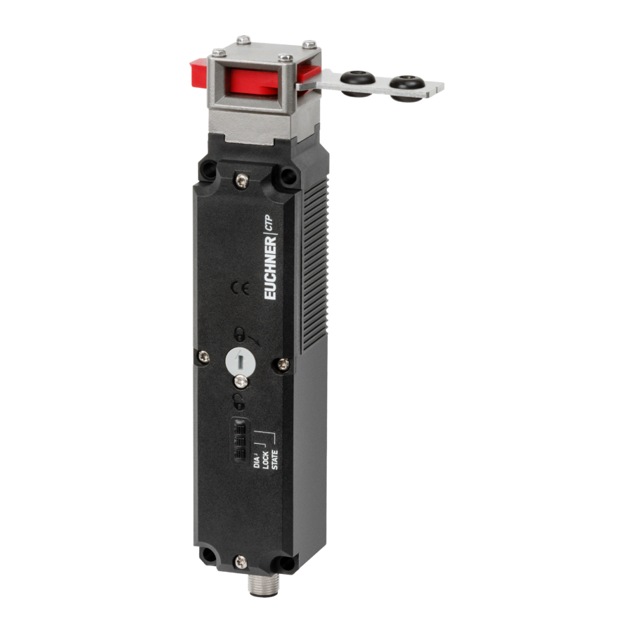
- Page 1 Operating Instructions Transponder-Coded Safety Switch with Guard Locking CTP/CTA-L1/2-BP Unicode/Multicode...
-
Page 2: Table Of Contents
6.2.7. Communication connection C ...................9 6.3. Version CTP/CTA Extended ......................9 6.4. Guard locking ..........................9 6.4.1. Guard locking on version CTP/CTA-L1 ................9 6.4.2. Guard locking on version CTP/CTA-L2 ................9 6.5. Switching states ...........................10 Manual release ....................11 7.1. Auxiliary release and auxiliary key release ..................11 7.1.1. - Page 3 6.4.1. Dimension drawing for safety switch CTP… ..............30 6.4.2. Dimension drawing for safety switch CTA… ..............31 6.4.3. Dimension drawing for connections and variants CTP/CTA … ...........32 6.5. Technical data for actuator CTP/CTA-… ..................33 6.5.1. Dimension drawing for actuator CTP/CTA-… ..............34 Ordering information and accessories ..............
-
Page 4: About This Document
1. About this document 1.1. Scope These operating instructions are valid for all CTP-L1/2-BP and CTA-L1/2-BP… from version V1.0.0. These operating instruc- tions, the document Safety information and any enclosed data sheet form the complete user information for your device. 1.2. -
Page 5: Correct Use
Ì EN 60204-1 The safety switch is allowed to be operated only in conjunction with the intended EUCHNER actuator and the related connec- tion components from EUCHNER. On the use of different actuators or other connection components, EUCHNER provides no warranty for safe function. -
Page 6: Description Of The Safety Function
Operating Instructions Transponder-Coded Safety Switch CTP/CTA-L1/2-BP 3. Description of the safety function Devices from this series feature the following safety functions: Monitoring of guard locking and the position of the guard (interlocking device with guard locking according to EN ISO 14119) Ì... -
Page 7: Exclusion Of Liability And Warranty
Operating Instructions Transponder-Coded Safety Switch CTP/CTA-L1/2-BP 4. Exclusion of liability and warranty In case of failure to comply with the conditions for correct use stated above, or if the safety regulations are not followed, or if any servicing is not performed as required, liability will be excluded and the warranty void. -
Page 8: Function
Operating Instructions Transponder-Coded Safety Switch CTP/CTA-L1/2-BP 6. Function The device permits the locking of movable guards. Transponder-coded actuator The system consists of the following components: coded actuator (transponder) and switch. Whether the device learns the complete actuator code (unicode) or not (multi- code) depends on the respective version. -
Page 9: Communication Connection C
6.4. Guard locking 6.4.1. Guard locking on version CTP/CTA-L1 (guard locking actuated by spring force and released by power-ON) Activating guard locking: close guard; no voltage at the solenoid. Releasing guard locking: apply voltage to the solenoid. -
Page 10: Switching States
Switching states The detailed switching states for your switch can be found in the system status table (see chapter 5. System status table CTP/CTA-L1/2-BP on page 26). All safety outputs, signals and display LEDs are described there. Guard closed and locked... -
Page 11: Manual Release
Operating Instructions Transponder-Coded Safety Switch CTP/CTA-L1/2-BP 7. Manual release Important! No further release functions can be retrofitted on Extended variants with control elements in position 1 (S1) and position 2 (S2). Some situations require the guard locking to be released manually (e.g. malfunctions or an emergency). A function test must be performed after release. -
Page 12: Actuating Auxiliary Key Release
Operating Instructions Transponder-Coded Safety Switch CTP/CTA-L1/2-BP 7.1.2. Actuating auxiliary key release On devices with auxiliary key release (can be retrofitted), simply turn the key to release. Function as for auxiliary release. For mounting, see the auxiliary key release supplement. 7.2. -
Page 13: Escape Release
7.3. Escape release The escape release is optional on CTP devices; on CTA devices it is optional or can be retrofitted. It permits opening of a locked guard from the danger zone without tools (see chapter 6.4.1. Dimension drawing for safety switch CTP… on page 30). -
Page 14: Laying Wire Front Release
Operating Instructions Transponder-Coded Safety Switch CTP/CTA-L1/2-BP 7.4.1. Laying wire front release Important! Ì Loss of the release function due to mounting errors, damage or wear. Ì Check the release function every time after mounting. Ì When routing the wire front release, ensure that it operates smoothly. -
Page 15: Mounting
The following specifications must be observed: - Mounting with screws of property class 8.8 or higher. - The minimum screw diameter for CTP devices is 4 mm, for CTA devices 5 mm. - Secure the fixing material against loosening (e.g. by means of medium-strength positive screw locking). -
Page 16: Electrical Connection
Operating Instructions Transponder-Coded Safety Switch CTP/CTA-L1/2-BP 5. Electrical connection WARNING In the event of a fault, loss of the safety function due to incorrect connection. Ì To ensure safety, both safety outputs FO1A and FO1B must always be evaluated. Ì... -
Page 17: Notes About
Operating Instructions Transponder-Coded Safety Switch CTP/CTA-L1/2-BP 5.1. Notes about Important! Ì This device is intended to be used with a Class 2 power source in accordance with UL1310. As an alternative an LV/C (Limited Voltage/Current) power source with the following properties can... -
Page 18: Requirements For Connecting Cables
Ì On the use of other connection components, the requirements in the following table apply. EUCHNER provides no warranty for safe function in case of failure to comply with these require- ments. Observe the following requirements with respect to the connecting cables: For safety switch CTP/CTA-…-BP-…-SII-…... -
Page 19: Connector Assignment Of Safety Switch Ctp/Cta
Operating Instructions Transponder-Coded Safety Switch CTP/CTA-L1/2-BP 5.5. Connector assignment of safety switch CTP/CTA-…-BP-…-SII-… with plug connectors 2 x M12 Conductor coloring Plug connector Designation Function of connecting (view of connection side) cable X 1.1 Electronics operating voltage, 24 V DC 2 x M12 X 1.2... -
Page 20: Connection
The switch can be reset via the RST input. To do this, a voltage of 24 V is applied to the RST input for at least 3 s. The RST input must be connected to 0 V if it is not used. If there is an internal error (see chapter 5. System status table CTP/CTA-L1/2-BP on page 26), the reset does not work. WARNING In the event of a fault, loss of the safety function due to incorrect connection. -
Page 21: Using Communication Data
Operating Instructions Transponder-Coded Safety Switch CTP/CTA-L1/2-BP 6. Using communication data A BR/IO-Link Gateway is required to use the device’s communication data and forward them to a higher-level bus system. The following devices are suitable: Ì GWY-CB-1-BR-IO (BR/IO-Link Gateway) Ì ESM-CB (safety relay with integrated BR/IO-Link Gateway) 6.1. -
Page 22: Acyclical Data (Device Data And Events)
Operating Instructions Transponder-Coded Safety Switch CTP/CTA-L1/2-BP 6.3.2. Acyclical data (device data and events) Table 4: Acyclical data (examples) Command Answer Use in device Meaning Category (number of bytes) classes General information Send device ID-number/ PWR-UP serial number Send device Versions... -
Page 23: Notes On Operation With Safe Control Systems
27. A detailed example of connecting and setting the parameters of the control system is available for many devices at www.euchner.com in the area Downloads/Applications/CTP… or CTA…. The features of the respective device are dealt with there in greater detail. -
Page 24: Setup
Operating Instructions Transponder-Coded Safety Switch CTP/CTA-L1/2-BP 7. Setup 7.1. LED displays You will find a detailed description of the signal functions in chapter 5. System status table CTP/CTA-L1/2-BP on page 26. Color STATE green LOCK yellow STATE LOCK 7.2. Teach-in function for actuator (only for unicode evaluation) The actuator must be allocated to the safety switch using a teach-in function before the system forms a functional unit. -
Page 25: Actuator Teach-In
Alternate flashing of the STATE and DIA LEDs acknowledges the successful teach-in operation. Teach-in errors are indicated by the illumination of the red DIA LED and a flashing code on the green STATE LED (see chapter 5. System status table CTP/CTA-L1/2-BP on page 26). 3. Switch off operating voltage U (min. -
Page 26: System Status Table Ctp/Cta-L1/2-Bp
Operating Instructions Transponder-Coded Safety Switch CTP/CTA-L1/2-BP 5. System status table CTP/CTA-L1/2-BP LED indicator Output Operating mode State 5 Hz Self-test after power-up Self-test 5 Hz 1 x No communication with the BR/IO-Link Gateway closed Normal operation, door closed and locked open Normal operation, door open, ready for guard locking... -
Page 27: Technical Data
Operating Instructions Transponder-Coded Safety Switch CTP/CTA-L1/2-BP 6. Technical data NOTICE If a data sheet is included with the product, the information on the data sheet applies. 6.1. Technical data for safety switch CTP-L1/2-BP Parameter Value Unit min. typ. max. General... -
Page 28: Technical Data For Safety Switch Cta-L1/2-Bp
Operating Instructions Transponder-Coded Safety Switch CTP/CTA-L1/2-BP Parameter Value Unit min. typ. max. Reliability values acc. to EN ISO 13849-1 Mission time years Monitoring of guard locking and the guard position Category Performance Level (PL) 5.38 x 10 Control of guard locking Category... -
Page 29: Typical System Times
Operating Instructions Transponder-Coded Safety Switch CTP/CTA-L1/2-BP Parameter Value Unit min. typ. max. Monitoring outputs OL/C, OI, OD 3 semiconductor outputs, p-switching, short circuit-proof Output voltage 0.8 x U V DC Max. load Solenoid Solenoid operating voltage U (reverse polarity protected, DC 24 V +10%/-15% regulated, residual ripple <... -
Page 30: Dimension Drawing For Safety Switch Ctp/Cta
Operating Instructions Transponder-Coded Safety Switch CTP/CTA-L1/2-BP 6.4. Dimension drawing for safety switch CTP/CTA… 6.4.1. Dimension drawing for safety switch CTP… Version with plug connector M12 With escape release The actuator shaft for the escape release can be extended using extensions (max. 94 mm) -
Page 31: Dimension Drawing For Safety Switch Cta
Operating Instructions Transponder-Coded Safety Switch CTP/CTA-L1/2-BP 6.4.2. Dimension drawing for safety switch CTA… Version with plug connector M12 With escape release The actuator shaft for the escape release can be extended using exten- sions (max. 94 mm) Basic position for escape release ∅... -
Page 32: Dimension Drawing For Connections And Variants Ctp/Cta
Operating Instructions Transponder-Coded Safety Switch CTP/CTA-L1/2-BP 6.4.3. Dimension drawing for connections and variants CTP/CTA … Plug connectors 2 x M12 Plug connector M12 Cable outlet C Cable outlet A Cable outlet C Cable outlet A With auxiliary key release With release, automatic return max. -
Page 33: Technical Data For Actuator Ctp/Cta
Operating Instructions Transponder-Coded Safety Switch CTP/CTA-L1/2-BP 6.5. Technical data for actuator CTP/CTA-… Parameter Value Unit min. typ. max. Housing material Fiber reinforced plastic 0.03 … 0.06 (depending on version) Weight Ambient temperature °C Degree of protection IP65/IP67/IP69/IP69K Mechanical life 1 x 10 Locking force (ISO 14119) -
Page 34: Dimension Drawing For Actuator Ctp/Cta
Operating Instructions Transponder-Coded Safety Switch CTP/CTA-L1/2-BP 6.5.1. Dimension drawing for actuator CTP/CTA-… Dimension drawing Min. door radius [mm] Order no./item 126015 A-C-H-G-SST-126015 Color: red Only for CTA max.28 165497 A-C-H-G-SSS-165497 Color: black (translation of the original operating instructions) 2537377-01-05/21... - Page 35 Operating Instructions Transponder-Coded Safety Switch CTP/CTA-L1/2-BP Dimension drawing Min. door radius [mm] Order no./item 37,5 122667 A-C-H-W-SST-122667 12,45 bent, upward max. 28 122668 A-C-H-W-SST-122668 5,25 bent, downward 2537377-01-05/21 (translation of the original operating instructions)
- Page 36 Operating Instructions Transponder-Coded Safety Switch CTP/CTA-L1/2-BP Dimension drawing Min. door radius [mm] Order no./item 3,25 122671 A-C-H-RL-LS-122671 max. 28 X = 53 mm (122671, 122672) X = 49 mm (122669, 122670) 122672 A-C-H-RR-LS-122672 122675 A-C-H-RO-LS-122675 max. 28 X = 41 mm (122673, 122674)
-
Page 37: Ordering Information And Accessories
7. Ordering information and accessories Tip! Suitable accessories, e.g. cables or assembly material, can be found at www.euchner.com. To order, enter the order number of your item in the search box and open the item view. Accessories that can be combined with the item are listed in Accessories. -
Page 38: Declaration Of Conformity
ET 18080* Azionatore Actuador 12.04.2021 - NG - GZ - Blatt/Sheet/ Page/Pagina/ Página 1 Vorlage Rev 01 EUCHNER GmbH + Co. KG Kohlhammerstraße 16 70771 Leinfelden-Echterdingen Tel. +49/711/7597-0 Fax +49/711/753316 www.euchner.de info@euchner.de (translation of the original operating instructions) 2537377-01-05/21... - Page 39 D irector de desarrollo electrónico Agente documentación 12.04.2021 - NG - GZ - Blatt/Sheet/ Page/Pagina/ Página 2 Vorlage Rev 01 EUCHNER GmbH + Co. KG Kohlhammerstraße 16 70771 Leinfelden-Echterdingen Tel. +49/711/7597-0 Fax +49/711/753316 www.euchner.de info@euchner.de 2537377-01-05/21 (translation of the original operating instructions)
- Page 40 Edition: 2537377-01-05/21 Title: Operating Instructions Transponder-Coded Safety Switch CTP/CTA-L1/2-BP (translation of the original operating instructions) Copyright: © EUCHNER GmbH + Co. KG, 05/2021 Subject to technical modifications; no responsibility is accept- ed for the accuracy of this information.
Need help?
Do you have a question about the CTP and is the answer not in the manual?
Questions and answers