Table of Contents
Advertisement
Quick Links
Advertisement
Table of Contents

Related Manuals for sitrex 1800


Summary of Contents for sitrex 1800
- Page 1 USE AND MAINTENANCE WRAPPER WR/1800-2100...
-
Page 3: Table Of Contents
SECTION 4 Instructions for use before use 4.1.1 operating position connection to a tractor 4.2.1 connection to tractor; "1800" and "carried 2100" 4.2.2 connection to tractor; towed version (2100) preparation of machine for use 4.3.1 hydraulic system connections 4.3.2 description of hydraulic controls filmstretcher 4.4.1... -
Page 4: Description And Main Features
- Personnel in charge of scrapping. and all other data deemed necessary for the user to gain familiarity with the bale wrapper «1800» e «2100», hereinafter also referred to as WARRANTY the machine. On delivery, check that the machine has not been... -
Page 5: Exclusions From Warranty
In the event the «1800» and « 2100» Bale Wrapping Machines machine is altered, following repairs carried out by bear the “CE” mark and comply with EC the user without the Manufacturer’s permission or... -
Page 6: Use For Which The Machine Is Not Designed
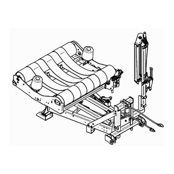
WARNING WARNING The bale loading, wrapping The values measured reveal and unloading operations must be made with that the machine has a high noise level. When the wheels or the feet on the soil. operating the machine, the operator must use ear protection, such as appropriate safety earmuffs or ear plugs, to prevent damage to hearing (including long-term effects). - Page 7 Fig.1 – View of the machine with its main component assemblies ROTATING CRADLE DRAW BAR WITH TOWING LINK (2100) SIDE SUPPORT ROLLERS HYDRAULIC DISTRIBUTOR BALE SUPPORT ROLLERS IDENTIFICATION PLATE BELTS MAIN FRAME BALE LOADER/UNLOADER FORK WHEELS WITH TYRES (2100) (2100) REARMAMENT CUTTING PLIERS SET STRETCHER FILM GROUP PLIERS INSERT AND CUTTER FILM...
-
Page 8: Technical Features "1800
1.7 TECHNICAL FEATURES «1800 » 1800 ODEL ALE OUTPUT PER HOUR 30 tours/min AX SPEED CRADLE ROTATION ONTROL NUMBER 12 V LECTRICAL FEEDING Optional (1 or 2) EEL SUPPORTS Fig.2 – Overall machine dimensions... -
Page 9: Technical Features "2100
1.8 TECHNICAL FEATURES « 2100 » 2100 ODEL ALE OUTPUT PER HOUR 30 tours/min AX SPEED CRADLE ROTATION ONTROLS NUMBER 12 V LECTRIC FEEDING Optional (1 or 2) EEL SUPPORTS Fig.2 – Overall machine dimensions... -
Page 10: Safety And Accident Prevention
term health hazards. SECTION 2 Safety and accident prevention CAUTION This symbol warns reader that, if the operations described are not performed properly, the machine may be 2.1 SAFETY damaged and/or persons injured The user is responsible for making sure the personnel is instructed on the hazards deriving 2.1.1 TERMINOLOGY USED from accidents, the devices fitted for the operator’s... -
Page 11: General Safety Instructions
The wrappers «1800» and « 2100» have been involved with possible fatal manufactured in conformity with the current consequences too. - Page 12 .- When taking corners with or without the machine loaded onto the tractor, be careful of centrifugal forces acting on points other than the centre of gravity. .- Connect the machine as described to a tractor with a suitable power output and configuration using the correct connection equipment (tow ring or support), in compliance with legislation.
-
Page 13: Operazioni Di Controllo Macchina
2.1.3 MACHINE CONTROL OPERATIONS CAUTION Occasionally check that all nuts and bolts are correctly tightened. If necessary to tight them again. Use of a torque wrench to set to the following tightening torque settings (in Nm): class Ø 10.9 M 10 M 12 M 14 M 16... -
Page 14: Safety Symbols
unauthorised persons near the machine or its controls during operation. 2.2 SAFETY SYMBOLS 8) Cod.89005005: Danger. Check the maximum vertical load exerted on the tow ring linking the This machine has been designed constructed machine to the tractor. incorporating all possible measures to ensure the safety of the operator. - Page 15 Fig. 4 SAFETY SYMBOLS AND THIER LOCATION ON THE MACHINE...
-
Page 16: Clothing
2.3 CLOTHING WARNING Always wear suitable clothing. Do not wear ties, necklaces or wide or loose clothing as they could become entangled in the rotating parts. Long hair must be tied up and kept out of the way. Always wear safety clothing such as cut- resistant gloves and slip-proof and crushproof shoes during maintenance and repair work. -
Page 17: Transporting And Moving
Should the machine have to be taken a long way, it can be loaded on a lorry or freight car. To this end, consult “1.7 Technical data” for the weight and SECTION 3 dimensions. dimensions particularly important in determining the feasibility of transport through tunnels or tight passages. - Page 18 WARNING Once the bale wrapper has been transferred onto the lorry or freight car, make sure it is firmly secured in place. The wheels must be secured by wedging suitable chocks under them. Fasten the machine securely to the surface on which it is set, using cables or chains, pulled tight and fastened to the hold- down point on the surface and appropriate for the weight of the machine to prevent the...
-
Page 19: Instructions For Use
4.2.1 CONNECTION TRACTOR; SECTION 4 “1800” AND “CARRIED 2100” Instructions for use To ensure a correct connection between bale wrapper and tractor, the following is necessary: -Position the machine on a level surface. -With the machine on the ground and the... -
Page 20: Preparation Of Machine For Use
FIG. 6 – MACHINE CONNECTIONS Fig.7 – CONNECTION TO TRACTOR Once drawbar ring been 4.3.2 DESCRIPTION OF HYDRAULIC connected to the (A Fig.5) tow hook, release CONTROLS the support foot and return it to its resting The hydraulic distributor remote control unit must position. -
Page 21: Filmstretcher
4.4 FILMSTRETCHER Fig.9 – Control distributor’s levers Lever A (only 2100) : Bale loader fork control. This lever controls the bale loading fork and allows to stop the bale on the cradle during loading and unloading operations. Lever B : Control cradle rotation This lever allows the cradle rotation to wrap the bale. -
Page 22: Reel Height Setting
Fig.11 – Stretching setting fig.13 – Filmstretching height Fig.12 – Stretching ratios It is always important to know that the stretch ratio of a film is also influenced by such factors as weather, machine operating temperature and humidity. The values given in the table are solely intended as guidelines. -
Page 23: Reel Installation
4.4.3 REEL INSTALLATION To install film reel you must to proceed as follows (fig.14): 1- Move the rolls away from the support reel pushing the lever (A). At the end of the stroke the rolls will be coupled up on the stop (B); 2- Push the upper plug (C) towards the top till hooking release. -
Page 24: Film Overlapping
4.5 FILM OVERLAPPING The bale wrap happens through combination of two movements: first movement along vertical axis rotation, which has given from the cradle, and the other along horizontal axis rotation, which has given from rolls rotation. The ratio between wrapped surface of the bale for every cradle tour and the stretched film height has called film overlapping level (fig.17). -
Page 25: Film Holder/Cutting Clamp
The functioning of holder/cutting device happens 2+2+2 Overlapping as follows: Film height Once wrapped the bale, during lifting of the (mm) cradle for unloading, a system with a cam close the pliers; at this phase the sliding blade Diameter Cradle tours has wound up by device (E) The film has blocked within plugs Used film (m) -
Page 26: General Checks To Be Made Before Wrapping
To put and to tighten again the fastening screws. To reinstall the gear and the case. fig.22 – Loading 1800 fig.21 – Setting rolls distance Model 2100: To centre the cradle. To move with the cradle to the bale and lift completely the fork (fig.9, lever... - Page 27 of the cutting pliers open it and the film has released. To set in action completely the rotation control wrap bale with To lift the fork to prepare the machine for wrapping. predetermined number of tours (note table of page 24).
- Page 28 At this moment it is possible to lower the fork to move with the wrapper in the near of following bale. fig.26 – Unloading 1800 Proceed with unloading operation (fig.9, lever C) till the complete lift of the cradle (fig.26). During this...
- Page 29 fig.28 – Release In case of doubts about functioning do not hesitate contact your area concessionaire explanations; we remember you that a correct functioning is the better guarantee for life of the machine.
-
Page 30: Indication For The Use
4.10.4 PREPARATION BALES FOR WRAPPING 4.10 INDICATION FOR THE USE Following these rules to prepare the bales 4.10.1 GENERALINSTRUCTIONS improves wrapping quality: Ensure that foreign objects, which could damage the film during wrapping, do not enter If the machine is used correctly, following the product to be ensiled by rolling the field in correct parameters, it will function efficiently giving spring... -
Page 31: Tips For Bale Wrapping
4.10.6 TIPS FOR BALE WRAPPING SECTION 5 -Regular maintenance of the machine, and in MAINTENANCE particular of the film tensioner assembly, and keeping the tensioner rollers clean can substantially influence ensilage quality. -The correct position of the film tensioner assembly 5.1 MAINTENANCE relative to the centre of the bale is important to ensure correct wrapping results. -
Page 32: After The First 10 Operating Hours
Apply a coat of rust protection to any worn parts. Repeat the following checks regularly. These checks must be also be carried out at the beginning of each season: 5.1.1 AFTER THE FIRST 10 OPERATING HOURS After the first 10 operating hours, check: -Check the overall condition of the machine. -
Page 33: Every 400 Operating Hours
5.1.4 EVERY 80 OPERATING HOURS Every 80 operating hours : To grease the rotating cradle (fig.30, R). 5.1.5 EVERY 400 OPERATING HOURS Every 400 operating hours : To change the rotating cradle angular transmission oil, using 0,8 Kg SAE 90 oil (fig.32, O). fig.32 –... -
Page 34: Checks And Adjustments
DANGER Replacing the clamp blade must be done with the clamp in its open position. Beware - danger of loss of fingers. fig.33 – Lubrication points of the stretcher CHECKS AND ADJUSTMENTS Set the cradle drive chain as fig.35 – Holder / cutting pliers follows: -Tip the cradle completely into the bale unloading position. -
Page 35: Preparation For Storage When Machine Is
PREPARATION FOR STORAGE WHEN MACHINE IS NOT IN At the end of the season, or if the machine is not going to be used for a prolonged period, the following is necessary: Wash the machine with water. Do not point the high pressure jet directly at the roller bearings. -
Page 36: Troubleshooting
5.6 TROUBLESHOOTING TROUBLE CAUSE REMEDY Stretch ratio to high Reduce the stretch ratio Rolls of PSU are blocked To check functioning of gear rolls Damaged film reel Check the state of the film Film tears during stretching Rotation speed to high Reduce the tractor engine rpm Irregularly shaped bale Improbe bale shape... -
Page 37: Fittings
SECTION 6 FITTINGS Programming of the MC 300 6.1 COMPUTER MC 300 – Double function: programming confirmation, and number of programmed The computer indicates to the operator the end of dressing. wrapping phase. With the MC 300 you could set Key B –... - Page 38 Zona Industriale-Viale Grecia, 8 06018 TRESTINA-(Perugia)-ITALY Tel. +39.075.8540021-Telefax +39.075.8540523 e-mail: sitrex@sitrex.it www.sitrex.com...
Need help?
Do you have a question about the 1800 and is the answer not in the manual?
Questions and answers