
Related Manuals for Daikin UATYQ20-115ABAY1


Summary of Contents for Daikin UATYQ20-115ABAY1
- Page 1 ESIE18-19A Roof Top Controller Application software UATYQ20~115A (BA-FC2-FC3) Y1 Issue 12/18...
- Page 2 We reserve the right to make changes without prior notice...
-
Page 3: Table Of Contents
TABLE OF CONTENTS 1 GENERAL ....................6 ............................6 ERSION LOG ........................6 URPOSE OF THE MANUAL ........................6 ONTROLLER FUNCTIONS ..............................6 YMBOLS ............................7 BBREVIATIONS 2 SYSTEM HARDWARE ................9 ........................... 9 ARDWARE PARTS ............................... 9 BOARD ..........................10 NTERFACE ............... - Page 4 6.3.2 Control logic of supply and return plug-fans on temperature setpoint ........35 6.3.3 Dampers management ......................36 6.3.3.1 Control logic of dampers ........................36 6.3.3.2 Minimum opening of recirculation damper ..................... 36 6.3.3.3 Reduction of minimum external air damper opening based on outdoor air temperature ....... 36 6.3.4 Automatic acquisition of air flow value as setpoint ..............
- Page 5 7.6.2 Configuration branch ........................59 7.6.3 Parameters branch ........................64 7.6.4 Timing branch ..........................68 7.6.5 Drivers branch ..........................70 7.6.6 Plug Fan branch ......................... 70 ............................72 SER MENU ..........................81 AINTENANCE MENU ............................85 LOCK MENU 7.9.1.1 Examples of time slot programming ...................... 87 7.10 S ............................
-
Page 6: General
1 GENERAL 1.1 Version log Version code Description Date ESIE18-19 Document release 17/12/2018 ESIE18-19A Page 6: 1.3 Controller functions 06/05/2019 Page 14: 2.5.2 Network component addressing Page 16: 3.1.2 Software addressing of the pCO* boards (no. 4 & 5) Page 31/32: 5.1.1 List of inputs and outputs Page 35: 6.3.2 Control logic of supply and return plug-fans on temperature setpoint Page 36: 6.3.3 Dampers management... -
Page 7: Abbreviations
1.5 Abbreviations Below is a list of the main abbreviations used in this manual. Any additional abbreviations will be illustrated in the relevant sections. Abbreviation Meaning Compressor 1, circuit 1 Compressor 2, circuit 1 Compressor 1, circuit 2 Compressor 2, circuit 2 No. - Page 8 SPnodfr Defrost de-activation threshold Air flow setpoint SpUR Relative ambient humidity setpoint Ambient temperature or return temperature External air temperature Delivery temperature TmLs Max. temperature in delivery line (summer mode) TmLw Max. temperature in delivery line (winter mode) Relative ambient or return humidity URae Relative external air humidity Neutral zone or dead zone...
-
Page 9: System Hardware
2 SYSTEM HARDWARE This chapter describes the constituting parts of the system, its accessories, if any, their connection and their functions. This chapter provides basic information on the controller software. For additional information, refer to the documentation supplied by the controller Manufacturer in the following website: http://www.carel.com 2.1 Hardware parts The controller consists of an I/O board featuring a micro processor controller and an internal memory. -
Page 10: User Interface
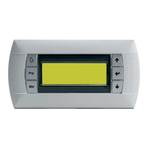
2.3 User Interface The user interface (Figure 2-2) consists of a backlit LCD monitor with 4 lines and 20 columns, intended for panel mounting. The display features 6 buttons to surf the software menus and to set the operating parameters. Figure 2-2 - User Interface Below is a description of the functions of the buttons. -
Page 11: Serial Boards For Connection To Control Systems
2.4 Serial boards for connection to control systems The controller is fitted with two Slave serial boards for connection to BMS control systems: a built-in serial board (BMS2 port) operates according to the Modbus RTU protocol; a housing for an additional serial board (BMS1 port), capable of fitting different boards depending on the selected communication system and protocol. -
Page 12: Installation Of Additional Serial Board
2.4.2.3 Installation of additional serial board The serial board needs to be installed in the “BMS card” slot in the controller board where a comb connector is provided. Below is a description of the procedure to be followed for serial board installation in the BMS1 slot. With the help of a flat head screwdriver remove the cover on the controller marked as “BMS card”. - Page 13 max 50 m If the terminal connection distance is over 50 m, but no longer than 200 m, 3 pairs of braided wires should be used, enclosed in a shielding having a cross-section of at least 0.5 sq.mm and T-switches (Carel code TCONN6J000), as shown in the figure.
-
Page 14: Connection Of Several Units To A Plan Local Network
2.5.1 Connection of several units to a pLAN local network If several units are installed serving one single location, they can be monitored, and their operating status viewed, with one shared display whose network address is “32”. The pCO boards in each unit must be interconnected in the pLAN local network using connector J11. Refer to the manual of the pCO board for connection instructions. -
Page 15: Programming Of Pco
3 PROGRAMMING OF PCO This chapter provides basic information for controller programming and addressing. For additional information, refer to the documentation supplied by the controller Manufacturer in the following website: http://www.carel.com Board programming means uploading the software in the controller board. The software may be uploaded in different ways, as illustrated below. -
Page 16: Procedure For The Identification Of The List Of Terminals For The Pco* Boards In The Network
3. Disconnect any other devices from the pCO* that are connected in pLAN (e.g. plug out connector J11). 4. Power the pCO* by pressing the “arrow up” and “Alarm” buttons simultaneously. Release the buttons when on the display appears the message “SELF TEST, PLEASE WAIT”; 5. - Page 17 The previous section describes the procedure for giving an address to the terminal, at the end of which, when the “enter” button is pressed, the user enters the procedure for addressing the terminals in the network, and the screen shown in the figure appears. Terminal config Press ENTER to continue...
-
Page 18: Network Error Messages
Terminal config Press ENTER to continue From this point on, the procedure continues as for six-button terminals. 3.1.4 Network error messages During operation of a network, connection and communication problems between the components may occur, in which case they will appear on the terminal of the network alarm screens; to resolve the problems, see the “Network troubleshooting”... -
Page 19: Files To Be Uploaded For Controller Programming
Example 1 -- - - - 8 - - - - - - - - 16 17 ▀ - ▀ - - - - - 24 25 - - - ▀ 32 In the network, there are two I/O boards with address 1 and 3, two private terminals with address 17 and 19, and there is also a shared terminal with address 32. -
Page 20: Programming Using A Smart Key
3.4 Programming using a Smart Key The Carel code in the programming key is PCOS00AKY0. Later in this manual the key will be referred to as “Smart Key”. The Smart Key enables software configurations to be transferred from computers to pCO controllers and vice versa. - Page 21 PCOS00A KC0 cavoUSB cavo telefonico USB cable telephone cable PCOS00A KC0 Smart Key connection to the computer As explained above, the key can be programmed with a computer through the "pco_manager" program. The functions enabled when the key is used can be set with the "pco_manager" program. The table below provides a list of the functions that are set up in the key.
- Page 22 WARNING If the key type is "B" or "C" (write mode), pressing the Start button causes immediate deletion of the software uploaded to the pCO. When the key is plugged into a pCO, the buttons and the symbols have the functions listed in the table. ...
-
Page 23: Programming Using The Pco Manager
Incompatibility between software application files and pCO mode flashing hardware. mode Symbols ON and Incompatibility between configuration hardware. flashing Space insufficient for log reading. Log data missing from pCO board. Key type not programmed. WARNING The key must not be plugged out while data is being written on it. The file being transferred may be lost and the corresponding space is not restored. - Page 24 The pCO5+ board can only read files stored in either the root directory of the pen drive or in a level one directory. After fitting the pen drive into the USB Host port in the board, press the Alarm and Enter buttons simultaneously for at least 3 seconds.
-
Page 25: Advanced History And Log Files
After upload completion, the following screen appears: Take out the USB pen drive and wait for the board rebooting. 3.7 Advanced history and log files If log generation files were uploaded into the board, as described above, some operating variables of the unit are logged whenever each programmed event occurs. - Page 26 DISPLAY LOG DATA Which Log? Xxxxxxxxxxx Once in the second level, the system requests selection of the history to read. The history log can be examined by event, i.e. parameters are recorded when an alarm triggers or an operating cycle gets started, or by cyclic records, i.e. parameters are recorded at predefined intervals. The last line shows the name of the history log, access to which is gained by pressing the Enter button.
-
Page 27: Log Downloading And Analysis Using A Personal Computer
The first line shows the date and time of the record. The arrow up and arrow down buttons are pressed to access the next record and the previous record respectively. The "Enter" button is clicked to access the values recorded at the selected date and time. DD-MM-YY HH:MM:SS XXXXXXXXXXXXXX... -
Page 28: Hardware Troubleshooting And Analogue Input Inspection
4 HARDWARE TROUBLESHOOTING AND ANALOGUE INPUT INSPECTION This chapter illustrates the most frequent hardware faults and gives some information on their possible causes and solutions. It also describes the procedure to be followed to check the analogue inputs in the controller board. -
Page 29: Analogue Input Testing
Problem Possible causes and solutions Questionable alarm message - Go to the relevant screen in the I/O branch and check the status of the from digital input input. - Check for voltage on the input involved between terminal "C" and corresponding terminal "Cn". -
Page 30: Ntc" And Pt1000 Passive Probes
voltage value measured in Volt; pressure value read on the controller. Example: Use a probe having an operating range between 0 and 30 bar, and a signal between 4 and 20 mA. Take the measurement between terminal “GND” and the connected input 630 mVdc: the pressure read by the controller is calculated as follows. -
Page 31: Inputs And Outputs
5 INPUTS AND OUTPUTS This chapter contains a list of the controller I/O (inputs and outputs). Inputs and outputs are used according to the actual configuration of the unit. 5.1.1 List of inputs and outputs The table below lists all the inputs and outputs featured in the controller. Main board Expansion board Differential pressure in air delivery line to fans... - Page 32 NO15 Free cooling/heating enabled NO16 Cycle reversing valve in circuit 2 NO17 Heating valve status NO18 Humidifier ON/OFF control External air damper Heat recovery analogue output Supply plug-fans Modulating control in humidifier Axial fans circuit 1 Hot water coil valve Return plug-fan Axial fans circuit 2 Recirculation air damper...
-
Page 33: Controller Logic
6 CONTROLLER LOGIC This chapter describes the logic of the controller fitted in roof top units. The unit you have purchased may not be provided with all the functions illustrated in this manual, because each unit is configured differently and has different accessories fitted. 6.1 General The main purpose of the controller installed in the unit is to preserve the temperature and humidity conditions in the place which is served by the roof top unit within the operating limits of the unit, as specified in the... -
Page 34: Switch-On Through An On/Off Digital Input
The time slots can be used to either start or stop the unit on condition that the remote ON/OFF digital input is closed (ref. to unit wiring diagram). Additionally, the daily time slots of screen K2 in the “Clock” menu must be enabled. -
Page 35: Control Logic Of Supply And Return Plug-Fans On Temperature Setpoint
The differential pressure value at the fan nozzle is measured by air pressure differential probes. The 0/10V control signal is sent to the fans only after closing of the digital output that controls the main ventilation system. When the unit off command is given, the digital output of the main ventilation system is opened on condition that the fan analogue signal is set to zero. -
Page 36: Dampers Management
6.3.3 Dampers management 6.3.3.1 Control logic of dampers This software allows to set two different logics for dampers (if presents) management: “PROPORTIONAL” or “LINEAR”. “PROPORTIONAL” logic drives the dampers in order to provide to the airflow an area, compared to the fully open area, equals to the required opening percentage. -
Page 37: Manual Operation
6.3.5 Manual operation Manual operation may be selected as an alternative to the air flow control system. This is how it is possible to directly set, within the expected limits, the value of the command signal to be sent to the fans, as an alternative to setting the air flow value. -
Page 38: Free Cooling
The controller automatically starts the compressors when the unit is in operation and there are no active alarms affecting either the entire unit or the compressors that are to be started. Compressors are started in sequence so as to minimise inrush currents. After a settable delay to unit start-up, the air flow switch input must get closed so that the controller can enable the compressors. -
Page 39: Air Heating
The setup values given to the parameters above help to control the priority of the cooling devices according to the combinations below: the free cooling damper is opened first; the compressors are only started after the damper has achieved its max. opening, if the ambient air temperature setpoint is not met; ... -
Page 40: Hot Water Coil Heating
6.4.2.2 Hot water coil heating Heating with a hot water coil is controlled by means of a water modulating valve. The controller manages opening of the valve within its corresponding differential (DHWV). The max. valve opening value is determined by an offset (OfsHWV) against the winter operating setpoint (SpH). -
Page 41: Free Heating
6.4.2.5 Free heating In units equipped with an external air damper the controller can use the external air conditions, where these are favourable in terms of temperature, to cool ambient air by properly managing opening of the external air damper. Damper modulation is implemented within the free heating differential (same value as free cooling), and it must be set with an offset with respect to the winter operating setpoint. -
Page 42: Combined Management Of Heating Devices
6.4.2.6 Combined management of heating devices If the unit is provided with multiple heating devices, such as a heat pump with a hot water coil, the controller can control these heating devices individually or in combined operation. Combined management of multiple heating devices is implemented by superimposing the activation differentials of the devices, keeping the winter setpoint as reference. -
Page 43: Air Humidification
6.4.3.2 Air humidification The controller manages signals that are used to control an external humidifier, which is either ON/OFF or modulating type. When the ON/OFF digital output is used for management, the OK signal to the humidifier is output when the ambient relative humidity (URa) is smaller than the setpoint value (SpUR) minus the neutral zone (ZNUR), if any, and the corresponding differential (DUR). -
Page 44: Damper Opening Control In Function Of Condensing/Evaporation Pressure
After enabling the air quality probe, the damper opening control is proportional. The damper starts opening at its min. opening value as soon as the air quality setpoint (SpCO ) plus the neutral zone (NZCO ), if any, is exceeded and it reaches its max. opening at the air quality setpoint (SpCO ) plus the air quality differential (DCO 6.4.5 Damper opening control in function of condensing/evaporation pressure... -
Page 45: Summer To Winter Mode Switching
6.5 Summer to Winter mode switching The unit is switched from summer (cooling) to winter (heating) operating mode in three different ways, depending on the setting in screen C6 of the Manufacturer menu. Switching may be commanded using the keyboard, a digital input and/or automatically. 6.5.1 Summer to Winter mode switching using the keyboard The keyboard can be used for switching on condition that the unit is turned to OFF. -
Page 46: Compressor Alternation And Power Equalisation
6.6.2 Compressor alternation and power equalisation Compressor alternation can be enabled to keep a balance in the number of hours of operation. Alternation is based on the FIFO principle (First In First Out). The first compressor on is also the first off. Similarly, the first compressor off is the first on. -
Page 47: High And Low Pressure Alarm Prevention Function
The control signal of the fans may range between the min. and max. setpoints. If the evaporation pressure rises above the setpoint, the analogue output preserves the min. setpoint value. When the evaporation pressure setpoint, increased by 1 bar, is reached, the controller zeroes the analogue output and disables the digital output. -
Page 48: Temperature-Driven Defrost
6.6.6.2 Temperature-driven defrost Temperature-driven defrost follows the same operating principle as pressure-driven defrost, the only difference being that the defrost threshold is expressed as a temperature value - not a pressure value - and it is compared with the evaporation temperature. 6.6.6.3 Variable defrost In conditions of low external air temperature the evaporation pressure of the unit reaches, on average, quite low values that are close to the “start defrost”... -
Page 49: External Air Damper Control Logic During Defrost
6.6.6.4 External air damper control logic during defrost In order to increase room comfort and to improve the performance of the refrigerant circuit when the unit is performing a defrost in heat pump mode, this software allows to enable the complete closing of the external air damper. -
Page 50: Secondary Functions
6.7 Secondary functions Below is a description of the controller secondary functions. 6.7.1 Dirty filters alarm If the unit is supplied with a filter differential pressure switch, the “dirty filters” alarm, which warns about excessive air filter fouling, is enabled when the digital input connected to the filter differential pressure switch is opened. -
Page 51: Setpoint Offset
6.7.4 Setpoint offset The setpoint offset function is designed to change the summer or the winter setpoint value depending on the external air temperature with the purpose of maximising the unit energy efficiency or to enhance comfort in the ambient. Summer offsetting is controlled by a differential which may be either positive or negative. -
Page 52: Enthalpy-Based Free Cooling/Free Heating
If you do not wish to use winter offsetting alone, and want to keep summer offsetting active, the winter offset setpoint must be entered with a value below the values that the air temperature is supposed to reach in winter. If you do not wish to use summer offsetting alone, and want to keep winter offsetting active, the summer offset setpoint must be entered with a value above the values that the air temperature is supposed to reach in summer. -
Page 53: Hot Water Anti-Freeze Function In Coil
between the measured enthalpy values is greater than the activation differential. Free cooling is active as long as the ambient enthalpy value equals the external enthalpy value, increased (first case) and reduced (second case) by the differential for enthalpy free cooling. EN (KJ) EN (KJ) Set EN... -
Page 54: Controller Screens
7 CONTROLLER SCREENS 7.1 General The controller screens are designed to view the operating status of the unit and its components and to set the operating parameters. The parameters and settings provided in this manual are mere examples. So, the values you will find in your unit may be different from those specified in this manual as they vary according to the unit size and configuration. -
Page 55: Screen Tree
7.2.1 Screen tree Below is the screen tree showing all the featured sub menus. Home screen M. Main menu N. Unit ON/OFF Z. Manufacturer V. Initialization C. Configuration G. Parameters T. Driver Timing F. EVD system parameters Q. Auto setup N. -
Page 56: Home Screen And Main Menu
7.4 Home screen and main menu As soon as the screen is switched on, the display shows the home screen M1 (the screen code is not displayed). Set 27.0°C 50.0% U01 Set 27.0°C Set 27.0°C 50.0% U01 27.0 50.0 27.0 50.0 27.0 50.0... -
Page 57: Unit On/Off Menu
Res.vasca cond. Cond.tray heater Res.tina cond. This screen only appears if the heater in the condensate tray in the unit has been enabled: it shows whether the heater is enabled. Gest.lavaggio Washing mng. Gestion lavado This screen only appears if a damper module is installed in the unit: it shows whether washing management is enabled. -
Page 58: Initialization Branch
Inserire Insert manuf. Insertar password password password 0000 0000 0000 To access the Manufacturer menu, it is necessary to enter the Manufacturer password; the default password is 0100. After entering the correct password, the sub menu of the Manufacturer branch appears, which shows 6 items: Initialization, Drivers, Plug fan, Configuration, Parameters and Timing. -
Page 59: Configuration Branch
7.6.2 Configuration branch The Configuration branch is used to set up the unit and to enable the featured accessories. Select the item “Configuration” in screen Z1 and press the Enter button to enter the Configuration branch. Screen "C0" appears on the display. Num.compressori Compressor num. - Page 60 Tipo sbrinamento C3B Defrost type Tipo descon. SCORREVOLE SLIDING POR PRESIóN Tipo sonda: Probe type: Tipo MODULANTE PRESSIONE PRESS. Deses.en PRESION This screen is used to set the defrost mode and the reference probe for defrost control. Tipo Type Tipo Refrigerant R410A Refrigerante...
- Page 61 Sonda temperatura C9 Enable supply Sonda temperatura C9 mandata temperature probe Impuls. Tipo NTC Type NTC Tipo NTC This screen is used to set the type of probe measuring the air temperature in the delivery line. The fourth line is used to set the probe type. Sonda umidità...
- Page 62 Limiti sonda CO2 CO2 air quality Limit. Sonda CO2 probe limits Limite min 0000ppm Min limit 0000ppm Limite min 0000ppm Limite max 2000ppm Max limit 2000ppm Limite max 2000ppm This screen is used to set the operating range of the air quality probe. The third line is used to set the min.
- Page 63 Recupero calore Heat Recovery Recuper. calor Logica uscita dig. Digital output Logica salida dig. N.C. Logic N.C. N.C. This screen is used to set the logic of the digital output for the heat recovery unit, if digital control of the bypass damper has been set in the Cq screen.
-
Page 64: Parameters Branch
Dati unità Unit data Datos unidad Matricola: 10012345 Serial n.: 10012345 N.de serie: 10012345 Data coll.: 01/01/18 Test data: 01/01/18 Data ens.: 01/01/18 Collaudatore: 0000 Tester: 0000 Ensayador: 0000 This screen is used to set the unit serial number, the factory acceptance testing date and the tester ID. The second line is used to set the unit serial number. - Page 65 This screen is used to select the de-activation of the air treatment fans during the defrost cycle and simultaneous defrosting of the refrigerant circuits. The second line in the screen is used to enable switch-off of the air treatment fans during the defrost cycle. The fourth line in the screen is used to enable simultaneous defrosting of the refrigerant circuits in units featuring two circuits.
- Page 66 The third line in the screen is used to set the pressure setpoint for evaporation control. The fourth line in the screen is used to set the pressure differential for evaporation control. Vent.est.2 comp. Ext.fans 2comp. Vent.est.2 comp. Velocità max a 07.5V Max speed at 07.5V Veloc.
- Page 67 The third line in the screen is used to set the evaporation pressure differential which enables restarting of the switched-off compressor as soon as the evaporation pressure reaches the setpoint plus the differential. The fourth line in the screen is used to set the delay to compressor switch-off when the pressure setpoint recorded in the second line is reached.
-
Page 68: Timing Branch
The third line in the screen is used to set the number of attempts required for automatic low pressure alarm resetting within the time span recorded in the next line. The fourth line in the screen is used to set the time span during which the attempts are run for automatic low pressure alarm resetting. - Page 69 Tempo tra On Time between ON Tempo ent/On stesso comp. 0300s same comp. 0300s mismo comp. 0300s Tempo tra On Time between ON Tiemp ent/On diversi comp. 0030s differ.comp. 0030s distin.comp. 0030s This screen is used to set the compressor times. The second line in the screen is used to set the min.
-
Page 70: Drivers Branch
7.6.5 Drivers branch This software version does not feature the Drivers branch screens. 7.6.6 Plug Fan branch The Plug fan branch is designed to configure plug type fans or inverter-controlled fans on both the delivery and return sides, where fitted, and to set the main parameters required to implement air flow control. Select the item “Plug fan”... - Page 71 This screen is used to set the min. and max. value range of the air flow on the return side. The third line in the screen is used to set the min. air flow on the return side. The fourth line in the screen is used to set the max. air flow on the return side. Allarme Sonda pre.Y6 Diff.al pressure Alarma sensor de...
-
Page 72: User Menu
If “Fan logic on Setpoint” is set to “SWITCH OFF” a” warning” appears (see below), that asks a confirmation for the activation of the function. In negative case, the controller set automatically the value “N”. The variable “Fan logic on Setpoint” is set to “N” by default. Attenzione!Solo per Warning!Only for uni Atencion!Solo para... - Page 73 This screen is used to set the min. and max. value range of the ambient temperature setpoint. The third line in the screen is used to set the min. ambient temperature setpoint. The fourth line in the screen is used to set the max. ambient temperature setpoint. Banda regol.temp.
- Page 74 Antigelo durante Antifreeze during PB Antihiel durante OFF unità unit OFF OFF unid. Set T.mandata 2.0°C Supply T.set 2.0°C Set T.impuls. 2.0°C Diff.T.mandata 0.5°C Supply T.diff. 0.5°C Dif.T.impuls. 0.5°C This screen is only displayed if the hot water coil is enabled as the heating device. It is used to set the temperature threshold in the air delivery line at which the hot water coil anti-freeze procedure gets started, and the differential beyond which the procedure stops when the unit is in OFF mode.
- Page 75 The fourth line in the screen is used to set the min. humidity setpoint. Banda reg.umidità Pc Humid.regul.band Banda reg.humedad Pc Estate 05.0%HR Summer 05.0%rH Verano 05.0%HR Inverno 05.0%HR Winter 05.0%rH Inviern 05.0%HR Zona neutra 05.0%HR Dead zone 05.0%rH Zona neutra 05.0%HR This screen is used to set the differentials and the neutral zone for humidity regulation in summer mode and in winter mode.
- Page 76 Freecool/heating Temperature Delta Differenziale in freecool/heating freecool/heating in temperatura 3.0°C activation delta temperatura 03.0°C 03.0°C This screen is used to set the air temperature differential for temperature-based regulation of free cooling/free heating. The third line in the screen is used to set the air temperature differential for temperature-based regulation of free cooling/free heating.
- Page 77 Gestione serrandePl1 Dampers control Pl1 Control compuertaPl1 Mode: PROPORTIONAL Tipo: PROPORCIONAL Tipo: PROPORZIONALE This mask allows to set the dampers control logic. “PROPORTIONAL” or “LINEAR” logic can be selected. “PROPORTIONAL” is the factory set value. Chiusura serranda Closing A.E. Cierre de compuerPl2 A.E.
- Page 78 Attivazione Heat recovery Activación recupero calore activation recuper. calor Delta temp. 04.0°C Delta temp. 04.0°C Delta temp. 04.0°C Diff. 01.0°C Diff. 01.0°C Dif. 01.0°C This screen is used to set the temperature difference between external air and ambient air, which is required for heat recovery activation, and the temperature differential required for modulating recovery damper opening.
- Page 79 This screen is used to configure the parameters required for communication with a supervisory control using controller port BMS2. The second line in the screen is used to set the number of communication bits. The third line in the screen is used to set the parity of communication. The fourth line in the screen shows the number of communication stop bits.
- Page 80 Ritardi sbrinam. P05 Defrost delays Retrasos descon. P05 Ingresso: 030s Start: 030s Entrada: 030s Forzato: 010s Forced: 010s Forzado: 010s This screen is only displayed if variable defrost is enabled. It is used to set the delay before switching to the defrost cycle and the delay in forced defrosting activation.
-
Page 81: Maintenance Menu
We recommend that the default password not be changed because the risk is that you can no longer access the protected menus if you forget the new password. If the password is changed, we recommend writing the new password down in the Notes pages at the end of this manual. - Page 82 The screen shows the hours of operation of compressors 1 and 2. Ore funzionamento A5 Working hours Horas func. Comp.3 000000h Compressor 3 000000h Comp.3 000000h Comp.4 000000h Compressor 4 000000h Comp.4 000000h The screen shows the hours of operation of compressors 3 and 4. Inserire Insert mainten.
- Page 83 Calibrazione Temperature Calibración sonda temperatura probe setting sonda temperatura Int. 00.0°C Int. 00.0°C Int. 00.0°C Man. 00.0°C Sup. 00.0°C Man. 00.0°C Calibrazione Temperature Calibración sonda temperatura probe setting sonda temperatura Est. 00.0°C Ext. 00.0°C Est. 00.0°C These screens are used to rectify the values measured by the temperature probes of the ambient air, the air in the delivery line and the external air.
- Page 84 WARNING! Resetting of the alarms history is an irreversible operation which causes all the alarms recorded in the History menu up to that moment to be lost. WARNING! The following screens are used to enable the controller digital outputs manually and to start the unit components individually for operational testing purposes.
-
Page 85: Clock Menu
If the unit features plug fans or inverter-controlled fans, including air flow rate control, the screen can be used to rectify the values measured by the air differential pressure probes in the delivery and return lines. We recommend that the value measured by a probe be rectified exclusively if the deviation from the measurement taken by a certified instrument exceeds 10 Pa. - Page 86 This screen is used to set the date and time: the day is selected automatically. Inserire Insert Insertar password password password 0000 0000 0000 Enter the password and press the Enter button: the default password is 0001. The following screens appear where the time slots can be set. Abilita fasce Daily time zone Habil.franjas...
-
Page 87: Examples Of Time Slot Programming
We recommend that the default passwords not be edited, otherwise access to password- protected branches may be prevented if they are not remembered. If the password is changed, we recommend writing the new password down in the Notes pages at the end of this manual. 7.9.1.1 Examples of time slot programming Below are two examples of time slot programming. -
Page 88: Setpoint Menu
Fasce orarie Time zone Fr. horarias Funz.invernale Winter working Func.invierno Set interno 20.5°C Internal set 20.5°C Set interno 20.5°C Set esterno 15.0°C External set 15.0°C Set externo 15.0°C Abilita OFF Unit OFF Habil. OFF unità da fascia by week time zone unid. -
Page 89: Inputs/Outputs Menu
Screen S4 is used to enable manual overriding of the air flow rate relating to the fans installed on the delivery and return lines. Setpoint Setpoint PConsig. Portata aria mandata Delivery air flow Flujo aire impuls. 009000m 009000m 009000m Screen S5 is used to set the air flow rate relating to the fans in the delivery line within the max. and min. values stored in screen Y4 of the “Plug fan”... - Page 90 Sonda temperatura I1 Temperature probe I1 Sonda temperatura I1 Supply 00.0°C Impuls. 00.0°C Mandata 00.0°C This screen shows the air temperature in the delivery line. Sonda umidità Humidity probe Sonda humedad Interna 00.0%Ur Intake 00.0%rH Interna 00.0%HR Esterna 00.0%Ur External 00.0%rH Externa 00.0%HR...
- Page 91 Ingressi digitali I9 Digital input Entradas digital. I9 13:CCC 16:CCC 13:CCC 16:CCC 13:CCC 16:CCC The screens show the status of the controller digital inputs: C = closed; O = open. Compressor 1 OFF Compressor 1 OFF Ia Compresor 1 OFF Ia Compressor 2 OFF Compressor 2 Compresor 2...
-
Page 92: History Menu
This screen shows the status of the GSM modem, where fitted, and the priority order of the contact numbers in the telephone book. Recupero calore Heat recovery Recuper. Calor Serranda by-pass Off By-pass damper Compuert by-pass Off Recupero calore Heat recovery Recuper. -
Page 93: Summer/Winter Menu
The first line in the screen shows the progressive alarm number, the time and date on which the alarm was recorded. The second and the third lines in the screen show the alarm message. The fourth line in the screen shows the ambient temperature and humidity at the time of alarm activation. Ambient humidity is only displayed if the corresponding probe is enabled. -
Page 94: Alarms
8 ALARMS When an alarm is activated, the red LED in the Alarm button flashes on the display and the corresponding alarm digital output is enabled. A click on the Alarm button causes the last active alarm to appear on the display. All the other alarms, if any, are scrolled ad viewed using the arrow buttons. - Page 95 DEVICES UNIT CODE DESCRIPTION MAIN CAUSE POTENTIAL RESOLUTION OF THE PROBLEM RESET SWITCHED Check the operating conditions. Check the condensing pressure. Check the refrigerant level. A high pressure alarm has triggered in High pressure Check the condensation fans. AL03 refrigerant circuit 1 generated by the compressors in in circuit 1 Manually reset the high pressure switch...
- Page 96 DEVICES UNIT CODE DESCRIPTION MAIN CAUSE POTENTIAL RESOLUTION OF THE PROBLEM RESET SWITCHED AL17 Not used Check the operating conditions (air flow rate and discharge head). The air flow switch has tripped: it Check the air delivery fans for correct indicates a lower air differential AL18 Flow switch alarm...
- Page 97 DEVICES UNIT CODE DESCRIPTION MAIN CAUSE POTENTIAL RESOLUTION OF THE PROBLEM RESET SWITCHED Check the operating conditions. Check the probe setpoint range stored in All devices and the controller. Probe U8 The value measured by probe U8 functions Test the probe: if it does not work AL27 malfunctioning or (external air temperature) is outside the...
- Page 98 DEVICES UNIT CODE DESCRIPTION MAIN CAUSE POTENTIAL RESOLUTION OF THE PROBLEM RESET SWITCHED Check the air flow rate in the return line. The differential air pressure probe in the Check the air distribution system. Differential probe in return line has detected a value outside Check for correct operation of the AL69 A (3)
- Page 99 DEVICES UNIT CODE DESCRIPTION MAIN CAUSE POTENTIAL RESOLUTION OF THE PROBLEM RESET SWITCHED Check the operating conditions. A high pressure alarm has triggered in Check the condensing pressure. refrigerant circuit 2 - heat pump mode - Circuit 2 Check the refrigerant level. generated by the pressure transducer.
-
Page 100: Quick Guide
9 QUICK GUIDE Below is a quick guide of the main controller functions. Keyboard-controlled unit switch-on and switch-off In the Main screen Prg select the “Unit On/Off” menu Enter Enter to switch the unit on or off. Editing the summer temperature setpoint In the Main screen ... - Page 101 Keyboard-controlled summer/winter mode switching Unit in OFF mode and keyboard-controlled summer/winter switching enabled in screen C6 of the Manufacturer menu In the Main menu Prg select the “Sum/Win.” menu Enter Enter to change the unit status. We reserve the right to make changes without prior notice...
-
Page 102: Procedures Required To Enable Accessories Supplied With The Unit
10 PROCEDURES REQUIRED TO ENABLE ACCESSORIES SUPPLIED WITH THE UNIT Below is a description of the procedures required to enable the accessories supplied with the unit. WARNING! The accessories supplied with the unit must be installed and enabled by qualified personnel, following the instructions provided in this manual and in the wiring diagram of the unit. -
Page 103: Remark Relating To Supervisory Control Protocols
10.4 Built-in Modbus RS485 serial board in BMS2 port Serial Modbus RS485 communication in the BMS2 port of the controller is enabled at all times. After connecting the serial cable coming from the supervisory control, screen Pq1 in the User menu can be used to set the communication baud rate (default 19200 bps), whereas the protocol is preset as Modbus. - Page 104 ______________________________________________________________________________________ ______________________________________________________________________________________ ______________________________________________________________________________________ ______________________________________________________________________________________ ______________________________________________________________________________________ ______________________________________________________________________________________ ______________________________________________________________________________________ ______________________________________________________________________________________ ______________________________________________________________________________________ ______________________________________________________________________________________ ______________________________________________________________________________________ ______________________________________________________________________________________ ______________________________________________________________________________________ ______________________________________________________________________________________ ______________________________________________________________________________________ ______________________________________________________________________________________ ______________________________________________________________________________________ ______________________________________________________________________________________ ______________________________________________________________________________________ ______________________________________________________________________________________ ______________________________________________________________________________________ ______________________________________________________________________________________ ______________________________________________________________________________________ ______________________________________________________________________________________ ______________________________________________________________________________________ ______________________________________________________________________________________ ______________________________________________________________________________________ ______________________________________________________________________________________ ______________________________________________________________________________________ ______________________________________________________________________________________ ______________________________________________________________________________________ ______________________________________________________________________________________ We reserve the right to make changes without prior notice...
Need help?
Do you have a question about the UATYQ20-115ABAY1 and is the answer not in the manual?
Questions and answers