Table of Contents
Advertisement
Quick Links
Advertisement
Table of Contents

Related Manuals for Shelly QUBINO Wave Pro 1PM


Summary of Contents for Shelly QUBINO Wave Pro 1PM
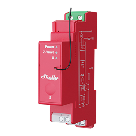
- Page 1 Wave Pro 1PM DIN-mountable Z-Wave® smart switch with power measurement functionality Extended User Guide (EN) Device: Wave Pro 1PM EU Part number/Ordering Code: QPSW-0A1P16EU Z-Wave Product type ID: 0x0002 Z-Wave Product ID: 0x008B Z-Wave Manufacturer: Shelly Europe Z-Wave Manufacturer ID: 0x0460...
-
Page 2: Table Of Contents
Table of contents Terminology ..........................5 1. About Shelly Qubino......................5 2. About the Device ........................6 3. Electrical diagrams 110-240 V AC ..................6 4. Installation instruction ......................7 5. About Z-Wave® ........................8 6. Z-Wave® Adding / Removing / Factory reset ................8 6.1 Adding the Device to a Z-Wave® network (inclusion) ............9 SmartStart adding (inclusion) ....................9... - Page 3 8.3 Output (O, O1, O2) LED....................16 9. Z-Wave® Parameters ......................17 Parameter No. 1 - SW (SW1) Switch type ................17 Parameter No. 2 - SW2 Switch type..................17 Parameter No. 17 - Restore the O (O1) state after a power failure ........17 Parameter No.
- Page 4 14. Technical Specifications ......................29 15. Important disclaimer ......................30 16. Declaration of Conformity ....................30 17. Manufacturer ........................31...
-
Page 5: Terminology
Terminology • Device - In this document, the term “Device” is used to refer to the Shelly Qubino device that is a subject of this guide. • Gateway (GW) - A Z-Wave® gateway, also referred to as a Z-Wave® controller, Z-Wave®... -
Page 6: About The Device
2. About the Device The Device is a DIN rail mountable smart switch with power measurement capabilities. It controls on/off function for one electrical device (with load up to 16 A), e.g., bulb, ceiling fan, IR heater, electrical locks, garage doors, irrigation system, etc. and it is compatible with push- buttons and switches (default). -
Page 7: Installation Instruction
Device terminals: • N: Neutral terminal • L: Live terminal (120 V AC 50/60 Hz) • SW (SW1): Input terminal for switch/push-button controlling O (O1) • SW2: Input terminal for switch/push-button • I: Input terminal for Load circuit • O (O1): Output terminal for Load circuit (1) Wires: •... -
Page 8: About Z-Wave
⚠CAUTION! Do not allow children to play with the push-buttons/ switches connected to the Device. Keep the devices for remote control of Shelly Qubino (mobile phones, tablets, PCs) away from children. ⚠CAUTION! Do not shorten the antenna. ⚠RECOMMENDATION: Place the antenna as far away as possible from metal elements as they can cause signal interference. -
Page 9: Adding The Device To A Z-Wave® Network (Inclusion)
6.1 Adding the Device to a Z-Wave® network (inclusion) Note! All Device outputs (O, O1, O2, etc. - depending on the Device type) will turn the load 1s on/1s off /1s on/1s off if the Device is successfully added to/removed from a Z-Wave® network. Note! In case of Security 2 (S2) adding (inclusion), a dialog will appear asking you to enter the corresponding PIN Code (5 underlined digits) that are written on the Z-Wave®... -
Page 10: Adding (Inclusion) With A Switch/Push-Button
Adding (inclusion) with a switch/push-button 1. Connect the Device to a power supply. 2. Check if the blue LED is blinking in Mode 1. If so, the Device is not added to a Z-Wave® network. 3. Enable add/remove mode on the gateway. 4. -
Page 11: Factory Reset
1. Connect the Device to a power supply. 2. Check if the green LED is blinking in Mode 1. If so, the Device is added to a Z-Wave® network. 3. Enable add/remove mode on the gateway. 4. Toggle the switch/push-button connected to any of the SW terminals (SW, SW1, SW2,…) 3 times within 3 seconds (this procedure puts the Device in Learn mode). -
Page 12: Remote Factory Reset With Parameter With A Gateway
4. The blue LED will be blinking in Mode 1 if the Factory reset is successful. Remote factory reset with parameter with a gateway Factory reset can be done remotely with the settings in Parameter No. 120. 7. Z-Wave® Security 2 and Device Specific Key (DSK) The Device supports the latest Security 2 (S2) feature. - Page 13 The first five digits of the key are highlighted or underlined to help the user identify the PIN Code part of the DSK text. The DSK is additionally represented with a QR Code as shown on the image. Z-Wave DSK label and QR code (example) A joining node requesting to join the S2 Access Control Class or the S2 Authenticated Class will obfuscate its Public Key by setting the bytes 1..2 to zeros (0x00) before transferring its key via The DSK may be used for out-of-band (OOB) authentication.
-
Page 14: Led Signalization
8. LED Signalization 8.1 Zwave LED 8.1.1 General rules • Switching between Normal and Settings mode is done by Single press on the S button • Solid LED means that you are in the Settings mode (this is not valid for Plugs). Ones in settings mode, switch to normal mode goes automatically after 10s •... -
Page 15: Settings Mode With S Button
During adding or removing, the LED will be blinking blue in Mode 2. OTA firmware updating During the OTA update, the LED will be blinking blue and red in Mode 2. Checking power supply 230 V AC frequency or 24 V DC voltage During checking the power supply, the LED will be blinking blue and red in Mode 5. -
Page 16: Alarm Mode
8.1.5 Alarm Mode Overcurrent detected O The LED will be blinking red in Mode 4 Overheat detected The LED will be blinking red in Mode 4 Power supply fault (power supply 230 V AC frequency or 24 V DC voltage fault) The LED will be blinking red in Mode 4 Overvoltage detected The LED will be blinking red in Mode 4... -
Page 17: Z-Wave® Parameters
9. Z-Wave® Parameters Parameter No. 1 - SW (SW1) Switch type This parameter defines how the Device should treat the switch (which type) connected to the SW (SW1) terminal. Value size: 1 Byte Default value: 2 Values & descriptions: • 0 - momentary switch (push button), •... -
Page 18: Parameter No. 19 - O (O1) Auto Off With Timer
• 1 - Device does not save on/off status and does not restore it after a power failure, it remains off Parameter No. 19 - O (O1) Auto OFF with timer If the load O (O1) is ON, you can schedule it to turn OFF automatically after the period of time defined in this parameter. -
Page 19: Parameter No. 25 - Set Timer Units To S Or Ms For O (O1)
Values & descriptions: • 0 - NO • 1 - NC Relay logic: Par-NO/NC Command (switch, Z-Wave…) Device output state NO (0) OFF (0 V) NO (0) ON (230 V) NC (1) ON (230 V) NC (1) OFF (0 V) Parameter No. -
Page 20: Parameter No. 39 - Minimum Time Between Reports (O) O1
NOTE: When the Device reports the power consumption (W), it will also automatically report the voltage (V) and current (A). NOTE: Regardless of the power consumption change in percentage, the report will not be sent more frequently than defined by Parameter No. 39. Parameter No. -
Page 21: Parameter No. 92 - Smoke Alarm
Parameter No. 92 - Smoke Alarm This parameter determines which alarm frames the Device should respond to and how. The parameters consist of 4 bytes, the three most significant bytes are set according to the official Z-Wave protocol specification. Values size: 4 Byte Default value: 0 Values &... -
Page 22: Parameter No. 120 - Factory Reset
• 0 no action • 1 open relay • 2 close relay Parameter No. 120 - Factory Reset Reset to factory default settings and removed from the Z-Wave network. The parameter is Advanced and may be hidden under the Advanced tag. Values size: 1 Byte Default value: 0 Values &... -
Page 23: Parameter No. 203 - Serial Number 3
Default value: Device specific Values & descriptions: 0x00000000 - 0x7FFFFFFF Parameter No. 203 - Serial Number 3 This parameter contains a part of device’s serial number. The parameter is Read-Only and cannot be changed. The parameter is Advanced and may be hidden under the Advanced tag. Values size: 4 Byte Default value: Device specific Values &... - Page 24 [S2]* Security S2 Command Class NOTE: MAPPING OF COMMAND_CLASS_BASIC Supporting Command Class Basic COMMAND_CLASS_BASIC is mapped into COMMAND_CLASS_SWITCH_BINARY, for enabling Switch (O) control: Switch (O) will be turned ON or OFF, after receiving the BASIC_SET command: Basic Command received Mapped Command (binary Switch) Basic Set (0xFF) Switch Binary Switch (0xFF) Basic Set (0x00)
-
Page 25: Z-Wave Notifications Command Class
Z-Wave Notifications Command class 11.1 Overheat detected Comment Overheat detected Z-Wave Notification Type Name Heat Alarm Z-Wave Notification type - Value 0x04 Z-Wave Notification type - Event State Z-Wave Notification Name Overheat detected Z-Wave Notification Name - Value 0x02 Z-Wave Notification Name - Version Check LED signalisation LED signalisation table... -
Page 26: Ac Mains Disconnected
Device reaction - Switch OFF the output O (O1) and send a notification Action to restore - power cycle Action to restore - short press on S button Action to restore - press any switch-push button connected to any SW (SW, SW1, SW2, …) terminal 11.3 AC mains disconnected AC mains disconnected (valid for AC Comment... -
Page 27: Z-Wave Associations
Z-Wave Notification Name Over-voltage detected Z-Wave Notification Name - Value 0x07 Z-Wave Notification Name - Version Check LED signalisation LED signalisation table Device reaction - Switch OFF all outputs and send notification Action to restore - power cycle Action to restore - short press on S button Action to restore - press any switch-push button connected to any SW (SW, SW1, SW2, …) terminal Z-Wave Associations... - Page 28 8. METER_REPORT: triggered by load power consumption connected to output O(O1) (according to the settings of Parameters No. 36 and 39) Root device - Association Group 2 Association Group 2 Allowed nodes: 9 It is assigned to switch connected to the SW (SW1) terminal (uses Basic command class). Triggered by SW (SW1).
-
Page 29: Supported Load Types
• SWITCH_MULTILEVEL_START_LEVEL_CHANGE: initiate a transition to a new level (increase or decrease light intensity in case of dimmer, or move shutter up or down, …) • SWITCH_MULTILEVEL_STOP_LEVEL_CHANGE: stop an ongoing transition (stop increase or decrease light intensity in case of dimmer, or stop moving shutter up or down, …) Supported load types •... -
Page 30: Important Disclaimer
Declaration of Conformity Hereby, Shelly Europe Ltd. (former Allterco Robotics EOOD) declares that the radio equipment type Wave 1 is in compliance with Directive 2014/53/ EU, 2014/35/EU, 2014/30/EU, 2011/65/EU. The full text of the EU declaration of conformity is available at the following internet address: https://shelly.link/WavePro1PM-DoC... -
Page 31: Manufacturer
Manufacturer Shelly Europe Ltd. (former Allterco Robotics EOOD) Address: 103 Cherni vrah Blvd., 1407 Sofia, Bulgaria Tel.: +359 2 988 7435 E-mail: zwave-shelly@shelly.cloud Support: https://support.shelly.cloud/ Web: https://www.shelly.com Changes in the contact data are published by the Manufacturer at the official website:...
Need help?
Do you have a question about the QUBINO Wave Pro 1PM and is the answer not in the manual?
Questions and answers