Table of Contents
Advertisement
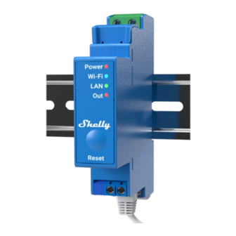
Wave Pro 1
DIN-mountable Z-Wave® smart switch with potential-
free contacts
Extended User Guide (EN)
Device: Wave Pro 1
EU Part number/Ordering Code: QPSW-0A1X16EU
AUS Part number/Ordering Code: QPSW-0A1X16AU
USA Part number/Ordering Code: QPSW-0A1X16US
Z-Wave Product type ID: 0x0002
Z-Wave Product ID: 0x008A
Z-Wave Manufacturer: Shelly Europe
Z-Wave Manufacturer ID: 0x0460
Advertisement
Table of Contents

Related Manuals for Shelly Wave Pro 1


Summary of Contents for Shelly Wave Pro 1
- Page 1 Wave Pro 1 DIN-mountable Z-Wave® smart switch with potential- free contacts Extended User Guide (EN) Device: Wave Pro 1 EU Part number/Ordering Code: QPSW-0A1X16EU AUS Part number/Ordering Code: QPSW-0A1X16AU USA Part number/Ordering Code: QPSW-0A1X16US Z-Wave Product type ID: 0x0002 Z-Wave Product ID: 0x008A...
-
Page 2: Table Of Contents
Table of contents 1. Terminology ..........................4 2. About Shelly Qubino ........................ 4 3. About the Device ........................5 4. Electrical diagrams 110-240 V AC .................... 5 Installation instruction ..................... 6 5. About Z-Wave® ........................7 6. Z-Wave® Adding / Removing / Factory reset ................8 Adding the Device to a Z-Wave®... - Page 3 10. Z-Wave Command Class ......................22 11. Z-Wave Notifications Command class ................... 23 11.1 Overheat detected ...................... 23 12. Z-Wave Associations ......................24 12.1 Root device ......................... 24 13. Supported load types ......................25 14. Technical Specifications ......................26 15. Important disclaimer ......................27 16.
-
Page 4: Terminology
1. Terminology • Device - In this document, the term “Device” is used to refer to the Shelly Qubino device that is a subject of this guide. • Gateway (GW) - A Z-Wave® gateway, also referred to as a Z-Wave® controller, Z-Wave®... -
Page 5: About The Device
3. About the Device The Device is a DIN rail mountable smart switch with potential-free contacts. It controls on/off function for one electrical device (with load up to 16 A), e.g., bulb, ceiling fan, IR heater, electrical locks, garage doors, irrigation system, etc. and it is compatible with push-buttons and switches (default). -
Page 6: Installation Instruction
⚠CAUTION! Do not allow children to play with the push-buttons/ switches connected to the Device. Keep the devices for remote control of Shelly Qubino (mobile phones, tablets, PCs) away from children. ⚠CAUTION! Do not shorten the antenna. -
Page 7: About Z-Wave
5. About Z-Wave® The Z-Wave® protocol is an interoperable, wireless, RF-based communications technology designed specifically for control, monitoring, and status reading applications in residential and light commercial environments. Mature, proven, and broadly deployed, Z-Wave® is by far the world market leader in wireless control, bringing affordable, reliable, and easy-to-use 'smart' products to millions of people in every aspect of daily life. -
Page 8: Z-Wave® Adding / Removing / Factory Reset
6. Z-Wave® Adding / Removing / Factory reset 6.1 Adding the Device to a Z-Wave® network (inclusion) Note! All Device outputs (O, O1, O2, etc. - depending on the Device type) will turn the load 1s on/1s off /1s on/1s off if the Device is successfully added to/removed from a Z-Wave® network. Note! In case of Security 2 (S2) adding (inclusion), a dialog will appear asking you to enter the corresponding PIN Code (5 underlined digits) that are written on the Z-Wave®... -
Page 9: Adding (Inclusion) With A Switch/Push-Button
Note! In Setting mode, the Device has a timeout of 10s before entering again into Normal mode. 6.1.3 Adding (inclusion) with a switch/push-button 1. Connect the Device to a power supply. 2. Check if the blue LED is blinking in Mode 1. If so, the Device is not added to a Z-Wave® network. -
Page 10: Removing (Exclusion) With A Switch/Push-Button
6.2.2 Removing (exclusion) with a switch/push-button 1. Connect the Device to a power supply. 2. Check if the green LED is blinking in Mode 1. If so, the Device is added to a Z-Wave® network. 3. Enable add/remove mode on the gateway. 4. -
Page 11: Remote Factory Reset With Parameter
3. During factory reset, the LED will turn solid green for about 1s, then the blue and red LED will start blinking in Mode 5 for approx. 2s. 4. The blue LED will be blinking in Mode 1 if the Factory reset is successful. 6.3.4 Remote factory reset with parameter Factory reset can be done remotely with the settings in Parameter No. - Page 12 The first five digits of the key are highlighted or underlined to help the user identify the PIN Code part of the DSK text. The DSK is additionally represented with a QR Code as shown on the image. Z-Wave DSK label and QR code (example) A joining node requesting to join the S2 Access Control Class or the S2 Authenticated Class will obfuscate its Public Key by setting the bytes 1..2 to zeros (0x00) before transferring its key via The DSK may be used for out-of-band (OOB) authentication.
-
Page 13: Led Signalization
8. LED Signalization 8.1 General rules • Switching between Normal and Settings mode is done by Single press on the S button • Solid LED means that you are in the Settings mode (this is not valid for Plugs). Ones in settings mode, switch to normal mode goes automatically after 10s •... -
Page 14: Settings Mode With S Button
OTA firmware updating During the OTA update, the LED will be blinking blue and red in Mode 2. Checking power supply 230 V AC frequency or 24 V DC voltage During checking the power supply, the LED will be blinking blue and red in Mode 5. 8.3 Settings mode with S button Adding / Removing menu selected When the menu is selected the LED will be on blue, for maximum of 10 seconds. -
Page 15: Alarm Mode
8.4 Alarm Mode Overheat detected The LED will be blinking red in Mode 4 8.5 Power LED LED type: Red The LED will be red solid if power supply is connected. 8.6 Output (O, O1, O2) LED LED type: Red The LED will be red solid if the Output relay is closed. - Page 16 Value size: 1 Byte Default value: 2 Values & descriptions: • 0 - momentary switch (push button), • 1 - toggle switch (contact closed - ON / contact opened - OFF), • 2 - toggle switch (device changes status when switch changes status) Parameter No.
- Page 17 Parameter No. 20 - O (O1) Auto ON with timer If the load O (O1) is OFF, you can schedule it to turn ON automatically after the period of time defined in this parameter. The timer resets to zero each time the Device receives an OFF command, either remotely (from the gateway or associated device) or locally from the switch.
- Page 18 Parameter No. 25 - Set timer units to s or ms for O (O1) Set the timer units to seconds or milliseconds. Choose if you want to set the timer in seconds or milliseconds in Parameters No. 19, 20. Values size: 1 Byte Default value: 0 Values &...
- Page 19 The notification types it reacts to are as followed, Notification Type: - NOTIFICATION_TYPE_SMOKE_ALARM 0x01 Notification Events: - NOTIFICATION_EVENT_SMOKE_ALARM_SMOKE_DETECTED 0x01 - NOTIFICATION_EVENT_SMOKE_ALARM_SMODE_DETECTED_UNKNOWN_LOCATION 0x02 Values size: 4 Byte Default value: 0 Values & descriptions: • 0 no action • 1 open relay •...
- Page 20 The notification types it reacts to are as followed, Notification Type: - NOTIFICATION_TYPE_HEAT_ALARM 0x04 Notification Events: - NOTIFICATION_EVENT_HEAT_ALARM_RAPID_TEMPERATURE_RISE_LOCATION_PROVIDED 0x03 - NOTIFICATION_EVENT_HEAT_ALARM_RAPID_TEMPERATURE_RISE 0x04 - NOTIFICATION_EVENT_HEAT_ALARM_RAPID_TEMPERATURE_FALL_LOCATION_PROVIDED 0x0C - NOTIFICATION_EVENT_HEAT_ALARM_RAPID_TEMPERATURE_FALL 0x0D Values size: 4 Byte Default value: 0 Values & descriptions: • 0 no action •...
- Page 21 Values & descriptions: 0x00000000 - 0x7FFFFFFF Parameter No. 202 - Serial Number 2 This parameter contains a part of device’s serial number. The parameter is Read-Only and cannot be changed. The parameter is Advanced and may be hidden under the Advanced tag. Values size: 4 Byte Default value: Device specific Values &...
-
Page 22: Z-Wave Command Class
Z-Wave Command Class 1. ASSOCIATION_V2 [S0, S2]* 2. ASSOCIATION_GRP_INFO_V3 [S0, S2]* 3. BASIC_V2 [S0, S2]* 4. SWITCH_BINARY_V2 [S0, S2]* 5. CONFIGURATION_V4 [S0, S2]* 6. DEVICE_RESET_LOCALLY_V1 [S0, S2]* 7. FIRMWARE_UPDATE_MD_V5 [S0, S2]* 8. INDICATOR_V3 [S0, S2]* 9. MANUFACTURER_SPECIFIC_V2 [S0, S2]* 10. MULTI_CHANNEL_ASSOCIATION_V3 [S0, S2]* 11. -
Page 23: Z-Wave Notifications Command Class
Z-Wave Notifications Command class 11.1 Overheat detected Comment Overheat detected Z-Wave Notification Type Name Heat Alarm Z-Wave Notification type - Value 0x04 Z-Wave Notification type - Event State Z-Wave Notification Name Overheat detected Z-Wave Notification Name - Value 0x02 Z-Wave Notification Name - Version Check LED signalisation LED signalisation table... -
Page 24: Z-Wave Associations
Z-Wave Associations Associations are used for direct communication between the Device and other devices within your Z-Wave network without the need of the Z-Wave gateway. Max. number of associated devices per group is 9. This value is fixed and can not be configured. Each association group supports the association of up to 9 devices (nodes). -
Page 25: Supported Load Types
It is recommended to use push buttons for this association. Supports the following command classes: • SWITCH_MULTILEVEL_START_LEVEL_CHANGE: initiate a transition to a new level (increase or decrease light intensity in case of dimmer, or move shutter up or down, …) •... -
Page 26: Technical Specifications
Technical Specifications Power supply 110 - 240 V Power consumption < 0.3W Max. switching voltage AC 240 V Max. switching current AC 16 A Max. switching voltage DC Max. switching current DC Overheating protection Power measurement Up to 40 m indoors (131 ft.) Distance (depends on local condition) Z-Wave®... -
Page 27: Important Disclaimer
Declaration of Conformity Hereby, Shelly Europe Ltd. (former Allterco Robotics EOOD) declares that the radio equipment type Wave 1 is in compliance with Directive 2014/53/ EU, 2014/35/EU, 2014/30/EU, 2011/65/EU. The full text of the EU declaration of conformity is available at the following internet address: https://shelly.link/WavePro1-DoC...
Need help?
Do you have a question about the Wave Pro 1 and is the answer not in the manual?
Questions and answers