Advertisement
Quick Links
Advertisement

Related Manuals for NCR Ingenico Lane 7000


Summary of Contents for NCR Ingenico Lane 7000
- Page 1 Kit Instructions PIN Pad Mount (Ingenico Lane 7000) 7370-K401 Issue A...
- Page 2 NCR, therefore, reserves the right to change specifications without prior notice. All features, functions, and operations described herein may not be marketed by NCR in all parts of the world. In some instances, photographs are of equipment prototypes. Software screen images are representative, and in some cases, may not match a customer’s installed software exactly.
-
Page 3: Revision Record
Revision Record Issue Date Remarks Jul 2022 First Issue... -
Page 4: Kit Contents
7370-K401 PIN Pad Mount (Ingenico Lane 7000) This publication provides procedures for installing a PIN Pad Mount for an Ingenico Lane 7000 device on the NCR FastLane SelfServ™ Checkout (7370) unit. Note: The Ingenico Lane 7000 PIN Pad is supplied by the customer. Kit Contents Part Number... -
Page 5: Installation Procedure
Installing the PIN Pad on page 8. Note: The Ingenico Lane 7000 PIN Pad is not included in the 7370-K401 PIN Pad Kit. For more information, contact an NCR Customer Service Representative. 4. Route the PIN Pad Cable. For more information, refer to Routing the PIN Pad cable page 10. - Page 6 7370-K401 PIN Pad Mount (Ingenico Lane 7000) Removing the PIN Pad Mount To remove the PIN Pad Mount, follow these steps: 1. Using a security hex key, remove one (1) M4x6 button head hex screw to detach the PIN Pad Mount from the PIN Pad Arm.
- Page 7 7370-K401 PIN Pad Mount (Ingenico Lane 7000) 2. Slide out the PIN Pad Mount form the slots on the PIN Pad Arm.
- Page 8 Removing the PIN Pad To remove the PIN Pad, follow these steps: Note: The Ingenico Lane 7000 PIN Pad is not included in the 7370-K401 PIN Pad Kit. For more information, contact an NCR Customer Service Representative. 1. Remove the PIN Pad Mount from the PIN Pad Arm. For more information, refer to Removing the PIN Pad Mount...
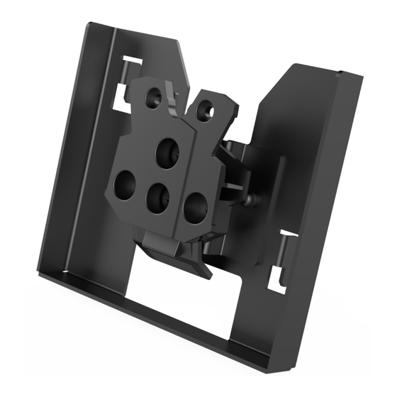
- Page 9 7370-K401 PIN Pad Mount (Ingenico Lane 7000) Installing the PIN Pad Mount To install the PIN Pad Mount, follow these steps: 1. Assemble the PIN Pad Mount by installing the Spacepole Multiclip to the PIN Pad Bracket using two (2) screws.
- Page 10 7370-K401 PIN Pad Mount (Ingenico Lane 7000) 2. Attach the PIN Pad to the PIN Pad Mount. a. Slightly tilt the PIN Pad and hook the upper part into the Spacepole Multiclip. b. Push the PIN Pad into the Spacepole Multiclip to secure it to the PIN Pad...
- Page 11 7370-K401 PIN Pad Mount (Ingenico Lane 7000) Installing the PIN Pad To install the PIN Pad, follow these steps: 1. Install the PIN Pad Mount. For more information, refer to Installing the PIN Pad Mount on page 6. 2. Slide the PIN Pad Mount into the slots on the PIN Pad Arm.
- Page 12 7370-K401 PIN Pad Mount (Ingenico Lane 7000) 3. Using a security hex key, secure the PIN Pad Mount to the PIN Pad Arm using one (1) M4x6 button head hex screw.
- Page 13 7370-K401 PIN Pad Mount (Ingenico Lane 7000) Routing the PIN Pad cable To route the PIN Pad Cable into the SelfServ Checkout unit, follow these steps: 1. Do the following: a. Connect the cable to the PIN Pad. b. Secure the cable to the PIN Pad Arm using cable ties.
- Page 14 7370-K401 PIN Pad Mount (Ingenico Lane 7000) 2. From the Tower Cabinet cable access hole, do the following: a. Route the cable along the wall of the Tower Cabinet. b. Secure the cable using cable ties. c. Pass the cable through the cable access hole at the rear of the Scanner Bucket, as shown in the example below.
- Page 15 7370-K401 PIN Pad Mount (Ingenico Lane 7000) 3. From the Tower Cabinet, do the following: a. Route the cable down the Pedestal Cabinet. b. Connect the PIN Pad Cable to the R6 I/O Box (USB H). Note: Keep the PIN Pad Cable (and other communications cables) away from and...
Need help?
Do you have a question about the Ingenico Lane 7000 and is the answer not in the manual?
Questions and answers