Advertisement
Quick Links
Advertisement

Related Manuals for NCR Ingenico iPP350


Summary of Contents for NCR Ingenico iPP350
- Page 1 KIT INSTRUCTIONS PIN Pad (Standard) - Ingenico Release 1.0 2368–K503 Issue A...
- Page 2 NCR, therefore, reserves the right to change specifications without prior notice. All features, functions, and operations described herein may not be marketed by NCR in all parts of the world. In some instances, photographs are of equipment prototypes. Therefore, before using this document, consult with your NCR representative or NCR office for information that is applicable and current.
- Page 3 Revision Record Issue Date Remarks Apr 2017 First Issue...
-
Page 4: Kit Content
PIN Pad (Standard) – Ingenico Introduction This kit provides the components to install an Ingenico (iPP350) PIN pad bracket to the NCR TouchPort 120 (2368) Kiosk. Kit Content... -
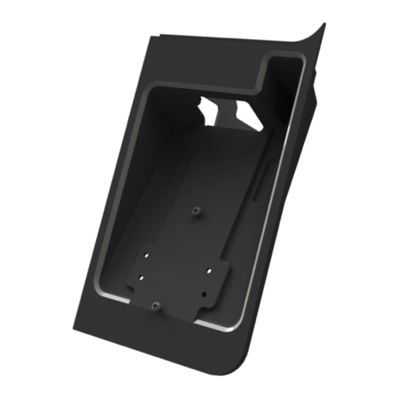
Page 5: Installation Instructions
Avoid any contact with internal parts and handle cards only by their external edges. To install the Ingenico PIN Pad to the NCR TP120 Self Check–In (2368) Kiosk, perform the following steps: 1. Mount the Ingenico Bracket to the Cradle. Slide down the cradle and tighten the... - Page 6 2368-K503 (PIN Pad Standard - Ingenico) 2. Mount the Ingenico PIN Pad to the bracket and cradle assembly. a. Align the slot on the lower back of the PIN pad with the small tab on the bracket. b. Route the PIN Pad cable out of the assembly. c.
- Page 7 2368-K503 (PIN Pad Standard - Ingenico) 3. Install the 3/8" P–Loop at the back of the bracket. Secure with screw (1). 4. Mount the Bracket on the PIN Pad assembly. Secure with screws (2).
- Page 8 2368-K503 (PIN Pad Standard - Ingenico) 5. Route the PIN pad cable through the P–Loop. 6. Turn the black plastic key counterclockwise to unlock the unit.
- Page 9 2368-K503 (PIN Pad Standard - Ingenico) 7. Pull the Countertop assembly.
- Page 10 2368-K503 (PIN Pad Standard - Ingenico) 8. Remove the screw beside the green plunger on each side of the unit and the screws (2) at the bottom of the Display Head assembly.
- Page 11 2368-K503 (PIN Pad Standard - Ingenico) 9. Pull the green plungers and twist it to a 90–degree angle on each linkage bracket, left and right, then lift the top of the unit forward until it stops. 10. Remove the MSR and NFC assembly installed on the left of the lower fascia. See Removing the MSR and NFC Assembly on page 10 11.
- Page 12 2368-K503 (PIN Pad Standard - Ingenico) 12. Tighten thumbscrews (2) to secure the assembly. 13. Connect the Ingenico PIN pad cable to the COM 1 port on the motherboard. Note: To prevent damage to the PIN pad cable, tuck it beside the Passport Reader. 14.
- Page 13 2368-K503 (PIN Pad Standard - Ingenico) Removing the MSR and NFC Assembly 1. Unplug the MSR USB Cable and Power Cable. 2. Remove the M4 nuts (4).
- Page 14 2368-K503 (PIN Pad Standard - Ingenico) 3. Remove the screw at the bottom of the MSR and NFC assembly. 4. Partially remove the MSR and NFC Assembly just enough to provide access to the cables.
- Page 15 2368-K503 (PIN Pad Standard - Ingenico) 5. Unplug the NFC Modular Jack from the controller receptacle and the NFC Antenna Wire from the NFC module.
Need help?
Do you have a question about the Ingenico iPP350 and is the answer not in the manual?
Questions and answers