
Related Manuals for SICK MCS100E HW


Summary of Contents for SICK MCS100E HW
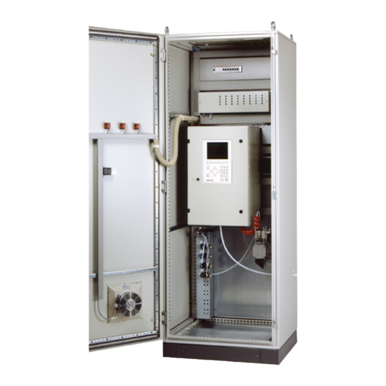
- Page 1 Front page M A I N T E N A N C E M A N U A L MCS100E HW Preventive Maintenance This Manual is intended exclusively for trained users. Unauthorized intervention voids the manufacturer's guarantee.
- Page 2 No guarantee claims shall be derived from the specified product characteristics and technical data as well as the described work sequences and conclusions. Subject to technical modifications. © SICK MAIHAK GmbH. All rights reserved. MCS100E HW Maintenance Manual 8009624/2009-09 (V 1.4) © SICK MAIHAK GmbH...
- Page 3 Risk or hazardous situation which could result in severe personal injury or death. CAUTION Hazard or unsafe practice which could result in less severe or minor injuries and/or property damage. MCS100E HW Maintenance Manual 8009624/2009-09 (V 1.4) © SICK MAIHAK GmbH...
-
Page 4: Table Of Contents
27 and 10 l/min. pump ........... 30 3.10 Leak tightness test of MCS100E HW sampling system ......39 3.11 Manual span gas feeding (viewing span gas concentrations) . -
Page 5: About This Manual
About this Manual MCS100E HW About this Manual Target group Special hazards Purpose of this Manual MCS100E HW Maintenance Manual 8009624/2009-09 (V 1.4) © SICK MAIHAK GmbH... -
Page 6: Target Group
1. 3 This Manual provides instructions concerning the preventive maintenance of the MCS100E The technical layout of the MCS100E HW in question can differ from the layout described in this Manual due to changes made by the manufacturer or customer. -
Page 7: Maintenance Interval
Maintenance Interval MCS100E HW Maintenance Interval Checklists Intervals MCS100E HW Maintenance Manual 8009624/2009-09 (V 1.4) © SICK MAIHAK GmbH... -
Page 8: Wearing Parts And Spare Parts
Number per maintenance interval (M = monthly/Q = quarterly/H = half-yearly/Y = yearly) As required For the compressed air station; as required Spare part Special tools and auxiliary equipment 2. 2 Please refer to the according chapter in this manual. MCS100E HW Maintenance Manual 8009624/2009-09 (V1.4) © SICK MAIHAK GmbH... -
Page 9: Maintenance Intervals
Check and adjust the flow monitor zero point → P. 40, § 3.11 Span gas feeding W = weekly, M = monthly, Q = quarterly, H = half yearly As required MCS100E HW Maintenance Manual 8009624/2009-09 (V 1.4) © SICK MAIHAK GmbH... - Page 10 Maintenance Interval MCS100E HW Maintenance Manual 8009624/2009-09 (V1.4) © SICK MAIHAK GmbH...
-
Page 11: Preventive Maintenance
Preventive Maintenance MCS100E HW Preventive Maintenance Detailed description MCS100E HW Maintenance Manual 8009624/2009-09 (V 1.4) © SICK MAIHAK GmbH... -
Page 12: Visual Inspection
Check zero gas flow 3. 3 1 View the "bar graph" display (F2 key). 2 Switch the MCS100E HW to "Stand-by". To do this: – Press the F3 function key. – Select "System Stop" (confirm safety prompt with "Yes"). – Exit the menu with "ESC" (otherwise the diagram will not be updated). -
Page 13: Maintenance Of The Compressed Air Station
Preventive Maintenance Maintenance of the compressed air station 3 . 4 Air station 5315575 and 5315576 3.4.1 These instructions are applicable for the SICK compressed air stations order number 5315575 (2-stages) and 5315576 (3-stages). Spare parts required Number Order No. - Page 14 3 Open the compressed air supply. Check pressures: – Pressure regulator inlet (right): Approx. 6 bar (according to your analyzer) – Pressure regulator outlet (left): Approx. 3 bar (according to your analyzer) MCS100E HW Maintenance Manual 8009624/2009-09 (V1.4) © SICK MAIHAK GmbH...
-
Page 15: Air Station 5309389
3 Drain liquid (oil or water) from both filter pots. To do this, pull drain slightly to the front. Check the drain for continuity and clean, if required. 4 When the filter pots are soiled: MCS100E HW Maintenance Manual 8009624/2009-09 (V 1.4) © SICK MAIHAK GmbH... - Page 16 If the protective cap jams: Push the plastic ring upwards with a finger nail 6 Open the compressed air supply. Check pressures: – Pressure regulator inlet (right): Approx. 6 bar – Pressure regulator outlet (left): Approx. 3 bar MCS100E HW Maintenance Manual 8009624/2009-09 (V1.4) © SICK MAIHAK GmbH...
-
Page 17: Check/Replace The Filter Pad In The Fan Of The Mcs100E Hw
As required The fan is located in the door of the MCS100E HW. It is not necessary to switch the MCS100E HW off to replace the filter pad. Risk of soiling. Operate the MCS100E HW without filter pad only for a short period. -
Page 18: Check The Flow Meter
MCS100E HW switching to "Störung/Error". 3 Wait until all measured values are shown as "0“. 4 Close the zero gas supply for MCS100E HW and FID (Oprion) at the compressed air sta- tion. 5 In the "flow" bar graph diagram, the flow meter must indicate a value slightly higher than "0"... -
Page 19: Maintenance Of The Gas Sampling Probe
Screw closure Pilot pins Guide slots a) Open the screw closures (Philips screwdriver). b) Pull the hood for weather protection away from the probe tube and take the hood off. MCS100E HW Maintenance Manual 8009624/2009-09 (V 1.4) © SICK MAIHAK GmbH... - Page 20 Provide a heat-resistant support as required. Caution: The filter cover is relatively heavy. Do not drop the cover. If the filter cover is hot: Place the filter cover on a heat-resistant mat. MCS100E HW Maintenance Manual 8009624/2009-09 (V1.4) © SICK MAIHAK GmbH...
- Page 21 6 Insert new bottom flat seal. Fig. 15 Seals of filter cover O-ring Flat seal 7 Replace O-ring and flat seal of filter cover. 8 Insert new or cleaned fine filter cartridge. MCS100E HW Maintenance Manual 8009624/2009-09 (V 1.4) © SICK MAIHAK GmbH...
- Page 22 Screw closure Pilot pins Guide slots 2 Press the screw closures in against the spring tension and screw tight. 3 If switched off: Switch the fuse in the measuring system on. MCS100E HW Maintenance Manual 8009624/2009-09 (V1.4) © SICK MAIHAK GmbH...
-
Page 23: Maintenance On The Sample Gas Pump (Heated)
Ensure adequate ventilation at the workplace or work under a vent. Wear protective goggles or a safety mask, protective gloves and acid- proof protective clothes. Fig. 18 View of the 18.5 l/min. pump MCS100E HW Maintenance Manual 8009624/2009-09 (V 1.4) © SICK MAIHAK GmbH... - Page 24 4 Remove the pump head and lay it down. Pay attention to the connections of the heating cartridge and the Pt100. MCS100E HW Maintenance Manual 8009624/2009-09 (V1.4) © SICK MAIHAK GmbH...
- Page 25 Intermediate plate 5 Remove the valve plates. 6 Remove the o-rings (only at yearly maintenance). 7 Remove the intermediate plate. Fig. 22 Pump membrane, pressure disk Pressure disk Pump membranes MCS100E HW Maintenance Manual 8009624/2009-09 (V 1.4) © SICK MAIHAK GmbH...
- Page 26 Cleaning Carefully clean the metal parts with compressed air, a cloth and, if required, fine emery cloth. Wash off with water. The metal surfaces must be dry, clean and smooth. MCS100E HW Maintenance Manual 8009624/2009-09 (V1.4) © SICK MAIHAK GmbH...
- Page 27 2 Fit the new pump membranes (3 pcs.) onto the pressure disk. „Upside“ doesn’t matter, but all membranes must have the same direction. Fig. 26 Membranes on pressure disk MCS100E HW Maintenance Manual 8009624/2009-09 (V 1.4) © SICK MAIHAK GmbH...
- Page 28 Threaded bolt 5 cup springs Bottom cup spring Fit the bottom cup spring with the concave side pointing upwards. Fit the remaining 5 cup springs with the concave sides pointing downwards. MCS100E HW Maintenance Manual 8009624/2009-09 (V1.4) © SICK MAIHAK GmbH...
- Page 29 The arrow tip must point towards the pump head. Use Teflon tape for screwing in. Final Steps 1 After installation of the pump in the system: Perform a leak test. MCS100E HW Maintenance Manual 8009624/2009-09 (V 1.4) © SICK MAIHAK GmbH...
-
Page 30: 27 And 10 L/Min. Pump
– Press the F3 function key. – Select "System Stop" (confirm safety prompt with "Yes"). 2. In the MCS100E HW, switch off the fuses of the pump motor and pump heating. WARNING: Hazard with wrong fuses If you switch the wrong fuse off, mains voltage is applied to the pump on which you are working. - Page 31 5 Remove the pump head and lay it down. Pay attention to the connections of the heating cartridge and the Pt100. Fig. 33 Pump head Heating cartridge and Pt100 connections MCS100E HW Maintenance Manual 8009624/2009-09 (V 1.4) © SICK MAIHAK GmbH...
- Page 32 Only use a well fitting 4 mm Allen key. Heat the Allen key to the temperature of the pressure disk. Otherwise you will severely damage the hexagon in the screw head. MCS100E HW Maintenance Manual 8009624/2009-09 (V1.4) © SICK MAIHAK GmbH...
- Page 33 Carefully clean the metal parts with compressed air, a cloth and, if required, fine emery cloth. Wash off with water. The metal surfaces must be dry, clean and smooth. MCS100E HW Maintenance Manual 8009624/2009-09 (V 1.4) © SICK MAIHAK GmbH...
- Page 34 2 Fit the lower pressure plate. The cone of the lower pressure plate must point down- wards. Do not shift the O-ring. Fig. 39 Lower pressure plate Lower pressure plate Cone O-ring MCS100E HW Maintenance Manual 8009624/2009-09 (V1.4) © SICK MAIHAK GmbH...
- Page 35 Intermediate plate Cutout Intermediate plate Line markings – According to line marking – The cutout for the valve plate must point to the top right (according to → Fig. 41). MCS100E HW Maintenance Manual 8009624/2009-09 (V 1.4) © SICK MAIHAK GmbH...
- Page 36 – The connections of the heating cartridge must point in the direction of the connec- tion box. The directional arrows on the pump head must point to the "left" (according to → Fig. 43). MCS100E HW Maintenance Manual 8009624/2009-09 (V1.4) © SICK MAIHAK GmbH...
- Page 37 Screw connection of pump head Cap nut Spacer bolt Cup springs 10 Fit the spacer bolts. 11 Fit the cap nuts and screw on up to the stop (not too tight). MCS100E HW Maintenance Manual 8009624/2009-09 (V 1.4) © SICK MAIHAK GmbH...
- Page 38 2. Switch on the fuses. 3 Perform a MCVS100E HW leak test (→ P. 39, § 3.10) 4 Switch the MCS100E HW to measuring mode with the F3 function key. – Press the F3 function key. – Select "System Start" (confirm safety prompt with "Yes").
-
Page 39: Leak Tightness Test Of Mcs100E Hw Sampling System
– Select "System Stop" (confirm safety prompt with "Yes"). 7 Switch the MCS100E HW to measuring mode. – Select "System Start" (confirm safety prompt with "Yes"). – Exit the menu with "ESC". MCS100E HW Maintenance Manual 8009624/2009-09 (V 1.4) © SICK MAIHAK GmbH... -
Page 40: Manual Span Gas Feeding (Viewing Span Gas Concentrations)
For the relation between the gas number (e.g. Gas 1) and the associated component (e.g.: HCl) refer to the system description supplied together with the MCS100E HW. Example: Fig. 48 Extract from the system description (the Section numbers only serve as examples) Key F7CAL MANU 4.6.1... - Page 41 5 Switch the MCS100E HW to measuring mode. – Select "System Start" (confirm safety prompt with "Yes"). – Exit the menu with "ESC". → P. 42, § 3.13 Span gas feeding for O MCS100E HW Maintenance Manual 8009624/2009-09 (V 1.4) © SICK MAIHAK GmbH...
-
Page 42: Manual Span Gas Feeding (Setting The Span Gas Concentration)
4 Confirm safety prompt with "Yes". Span gas feeding is performed automatically. The span gas concentration is corrected automatically. 5 The MCS100E HW switches automatically to measuring mode after span gas feeding has finished. MCS100E HW Maintenance Manual 8009624/2009-09 (V1.4) © SICK MAIHAK GmbH... -
Page 43: Attach The Screw Fitting
1 Begin with the first (innermost) turn of the screw fitting and wrap the sealing tape around the thread in approx. 3 to 4 layers in the direction of the thread with a slight overlap for each layer. 2 Screw the screw fitting in. MCS100E HW Maintenance Manual 8009624/2009-09 (V 1.4) © SICK MAIHAK GmbH... - Page 44 Preventive Maintenance MCS100E HW Maintenance Manual 8009624/2009-09 (V1.4) © SICK MAIHAK GmbH...
- Page 45 Wearing parts ....... 8 MCS100E HW Maintenance Manual 8009624/2009-09 (V 1.4) © SICK MAIHAK GmbH...
- Page 46 You will find our local subsidiary or agency at: www.sick.com Your local sales and service partner SICK MAIHAK GmbH | Germany Nimburger Str. 11 | 79276 Reute | www.sick.com Phone +49 7641 469-0 | Fax +49 7641 469-11 49 | info.pa@sick.de...
Need help?
Do you have a question about the MCS100E HW and is the answer not in the manual?
Questions and answers